am3zzw00017730
|
BRAKE PEDAL REMOVAL/INSTALLATION [L.H.D.]
id041100801250
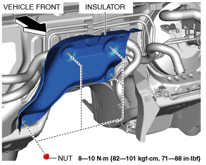
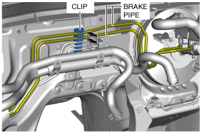
1. For SKYACTIV-D 1.5, perform the following procedure:
am3zzw00017730
|
am3zzw00017731
|
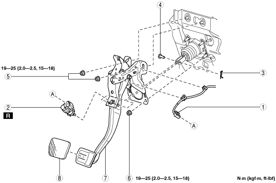
2. Remove in the order indicated in the table.
3. Install in the reverse order of removal.
am3uuw00010881
|
|
1
|
Brake switch connector and wiring harness
|
|
2
|
Brake switch
|
|
3
|
Snap pin
(See Snap Pin Installation Note.)
|
|
4
|
Clevis pin
|
|
5
|
Nut
|
|
6
|
Nut
|
|
7
|
Brake pedal
(See Brake Pedal Removal Note.)
|
|
8
|
Pedal pad
|
Brake Pedal Removal Note
1. Move the power brake unit to the vehicle front where the power brake unit fork does not interfere with the brake pedal arm.
2. Remove the brake pedal.
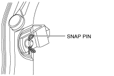
Snap Pin Installation Note
1. Install the snap pin as shown in the figure.
am3zzw00015871
|
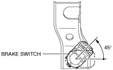
Brake Switch Installation Note
1. Inspect the brake pedal. (See BRAKE PEDAL INSPECTION.)
2. With the brake pedal fully released, insert a new brake switch into the installation hole on the brake pedal.
3. Secure the brake switch by turning it counterclockwise 45°.
ac5wzw00000204
|