DTC P0711:00 [FN4A-EL]


id050218817300

DTC P0711:00

TFT sensor circuit range/performance

DETECTION CONDITION
•  Under the following conditions, a difference of the input voltage from TFT sensor is 29.3 mV or less.
―  Time since engine starting is 180 s or more
―  ATF temperature is 40 °C {104 °F} or less
―  Vehicle speed is 26 km/h {16 mph} or more for 90 s
―  Vehicle speed is 61 km/h {38 mph} or more for 60 s
―  Selector lever position is D or M position
―  Accelerator pedal is not released
―  DTCs relating TFT sensor are not stored
―  Input voltage from TFT sensor is 4.668 V or less
Diagnostic support note
•  The check engine light illuminates if the PCM detects the above malfunction condition in two consecutive drive cycles or in one drive cycle while the DTC for the same malfunction has been stored in the PCM.
•  The automatic transaxle warning light does not illuminate.
•  PENDING CODE is available.
•  FREEZE FRAME DATA is available.
•  The DTC is stored in the PCM memory.
POSSIBLE CAUSE
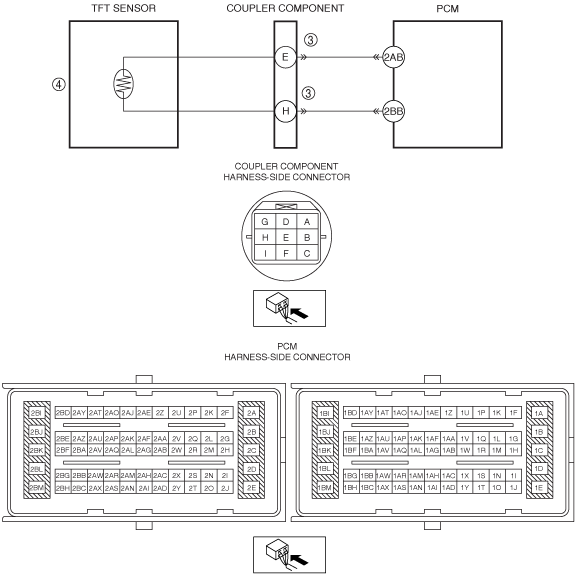
•  Coupler component connector or terminal malfunction
•  TFT sensor malfunction
•  PCM malfunction

Diagnostic procedure

STEP

INSPECTION

ACTION

1
VERIFY FREEZE FRAME DATA HAS BEEN RECORDED
•  Has the FREEZE FRAME DATA been recorded on the repair order?
Yes
Go to the next step.
No
Record the FREEZE FRAME DATA on the repair order, then go to the next step.
2
VERIFY RELATED REPAIR INFORMATION AVAILABILITY
•  Verify related Service Information availability.
•  Is any related repair information available?
Yes
Perform repair or diagnosis according to the available repair information.
•  If the vehicle is not repaired, go to the next step.
No
Go to the next step.
3
INSPECT COUPLER COMPONENT CONNECTOR FOR POOR CONNECTION
•  Switch the ignition off.
•  Disconnect the coupler component connector.
•  Inspect for poor connection (such as damaged/pulled-out pins, corrosion)
•  Is there any malfunction?
Yes
Repair or replace the terminal, then go to Step 5.
No
Go to the next step.
4
INSPECT TFT SENSOR
•  Is there any malfunction?
Yes
Replace the coupler component, then go to next step.
No
Go to the next step.
5
VERIFY DTC TROUBLESHOOTING COMPLETED
•  Make sure to reconnect all the disconnected connectors.
•  Clear the DTC using the M-MDS.
•  Perform the following procedure to ensure that the DTC has been resolved:
1.  Start the engine.
2.  Idle the engine for 180 s or more.
3.  Verify that ATF temperature (PID item: TFT) is 40 °C {104 °F} or less.
4.  Verify that input voltage from TFT sensor (PID item: TFTV) is 4.668 V or less.
5.  Select the selector lever to D or M position.
6.  Drive the vehicle at 26 km/h {16 mph} or more for 90 s or more.
7.  Drive the vehicle at 61 km/h {38 mph} or more for 60 s or more.
•  Is the same DTC present?
Yes
Replace the PCM, then go to the next step.
No
Go to the next step.
6
VERIFY NO DTCs ARE PRESENT
•  Perform the “Reading DTCs Procedure”.
•  Are any DTCs present?
Yes
Go to the applicable DTC inspection.
No
DTC troubleshooting completed.