DUAL-MASS FLYWHEEL INSPECTION [C66M-R]
id0510ma157800
SKYACTIV-G 2.5, SKYACTIV-D 1.5
-
Caution
-
• Do not rework the dual-mass flywheel if it is distorted.
• Do not clean the dual-mass flywheel with any kind of fluid. Clean the dual-mass flywheel with a dry cloth only.
• Do not clean the gap between the primary and secondary mass. Only clean the bolt connection surface and the clutch surface.
1. Remove the manual transaxle. (See MANUAL TRANSAXLE REMOVAL/INSTALLATION [C66M-R (SKYACTIV-G 1.5, SKYACTIV-G 2.0, SKYACTIV-G 2.5)].) (See MANUAL TRANSAXLE OIL REPLACEMENT [C66M-R] (SKYACTIV-D 1.5).)
2. Remove the clutch cover and clutch disc. (See CLUTCH UNIT REMOVAL/INSTALLATION [C66M-R].)
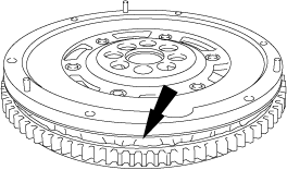
3. Inspect the rotation of the dual-mass flywheel for play.
- (1) Lock the dual-mass flywheel using the SST (49 E011 1A0).
-
- (2) Rotate the secondary flywheel clockwise by hand until resistance can be felt.
-
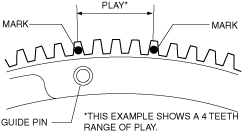
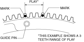
- (3) Mark the guide pin position on the ring gear of the flywheel.
-
- (4) Rotate the secondary flywheel counterclockwise by hand until resistance can be felt.
-
- (5) Mark the guide pin position on the ring gear of the primary flywheel again.
-
- (6) Verify that the play is within the range of 4 teeth. (SKYACTIV-G 2.5)
-
-
-
Caution
-
• It may not be possible to rotate the secondary flywheel due to the functionality of the dual-mass flywheel.
In this case, the dual-mass flywheel can be considered normal by reason of the play being within the range of 4 teeth.
- (7) Verify that the play is within the range of 3 teeth. (SKYACTIV-D 1.5)
-
-
-
Caution
-
• It may not be possible to rotate the secondary flywheel due to the functionality of the dual-mass flywheel.
In this case, the dual-mass flywheel can be considered normal by reason of the play being within the range of 3 teeth.
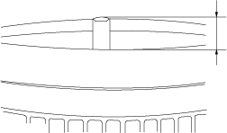
4. Measure the amount of guide pin projection of the dual-mass flywheel.
-
-
Dual-mass flywheel guide pin projection maximum amount
-
11.0—12.0 mm {0.434—0.472 in}
5. Remove the dual-mass flywheel. (See CLUTCH UNIT REMOVAL/INSTALLATION [C66M-R].)
6. Visually inspect the dual-mass flywheel for crack.
-
• If there is any crack, replace the dual-mass flywheel.
7. Visually inspect the ring gear on the dual-mass flywheel for damage.
-
• If there is any damage, replace the dual-mass flywheel.
8. Visually inspect the surface that contacts the clutch disc for scratches, nicks, and discoloration.
-
• If there is any malfunction, replace the dual-mass flywheel.
-
Note
-
• Correct slight scratches and discoloration using sandpaper.
9. Visually inspect for grease leakage between the primary mass and secondary mass.
-
• If there is grease leakage, replace the dual-mass flywheel.
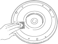
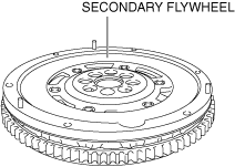
10. Place the dual-mass flywheel on the surface plate so that the secondary flywheel is pointed upward.
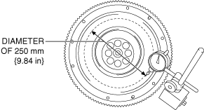
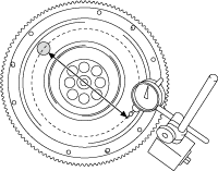
11. Set the dial gauge and magnetic stand on the surface plate.
12. Set the dial gauge pointer to the desired position at a diameter of 250 mm {9.84 in} around the center on the secondary flywheel.
13. Apply a load of approx. 50 N {5.1 kgf, 11 lbf} to the friction surface which is opposed 180 degree to the dial gauge end, and measure the oscillation amount of the dial gauge.
-
• If the oscillation amount of the dial gauge exceeds the allowance, replace the dual-mass flywheel.
-
Dual-mass flywheel oscillation allowance
-
1.5 mm {0.059 in}