 |
am3zzw00020875
CLUTCH UNIT REMOVAL/INSTALLATION [C66M-R]
id0510ma157200
SKYACTIV-G 1.5, SKYACTIV-G 2.0
1. Disconnect the negative battery cable. (See NEGATIVE BATTERY CABLE DISCONNECTION/CONNECTION [SKYACTIV-G 1.5, SKYACTIV-G 2.0, SKYACTIV-G 2.5].)
2. Remove the MTX. (See MANUAL TRANSAXLE REMOVAL/INSTALLATION [C66M-R (SKYACTIV-G 1.5, SKYACTIV-G 2.0, SKYACTIV-G 2.5)].)
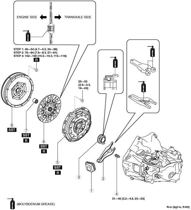
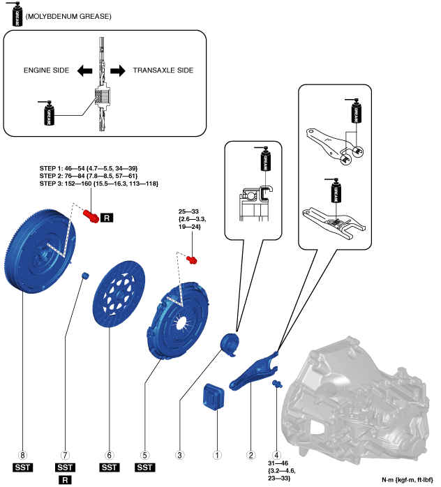
3. Remove in the order indicated in the table.
4. Install in the reverse order of removal.
5. Add the specified amount of specified manual transaxle oil. (See MANUAL TRANSAXLE OIL REPLACEMENT [C66M-R].)
am3zzw00020875
|
|
1
|
Boot
|
|
2
|
Clutch release fork
|
|
3
|
Clutch release collar
|
|
4
|
Pivot pin
|
|
5
|
Clutch cover
|
|
6
|
Clutch disc
|
|
7
|
Pilot bearing
|
|
8
|
Plate
|
|
9
|
Flywheel
|
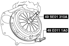
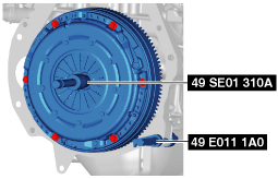
Clutch cover and clutch disc removal note (SKYACTIV-G 1.5, SKYACTIV-G 2.0)
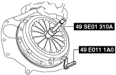
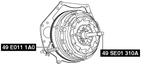
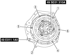
1. Hold the clutch unit using the SSTs (49 SE01 310A, 49 E011 1A0).
am3uuw00008262
|
2. Loosen each bolt one turn at a time in a crisscross pattern until spring tension is released.
3. Remove the clutch cover and disc.
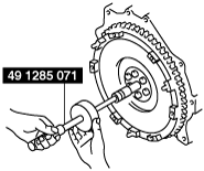
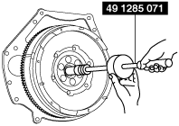
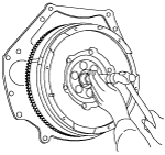
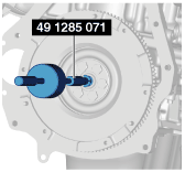
Pilot bearing removal note (SKYACTIV-G 1.5, SKYACTIV-G 2.0)
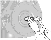
1. Use the SST (49 1285 071) to remove the pilot bearing.
am3uuw00002082
|
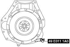
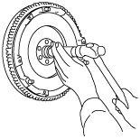
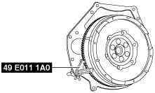
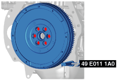
Flywheel removal note (SKYACTIV-G 1.5, SKYACTIV-G 2.0)
1. Hold the flywheel using the SST (49 E011 1A0).
am3zzw00014931
|
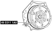
2. Remove the lock bolts, and remove the plate and the flywheel.
3. Inspect for oil leakage from the crankshaft rear oil seal.
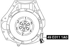
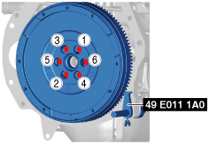
Flywheel installation note (SKYACTIV-G 1.5, SKYACTIV-G 2.0)
1. Degrease and clean the flywheel.
2. Clean the crankshaft thread holes.
3. Install the flywheel and the plate to the crankshaft, and temporarily tighten a new lock bolts.
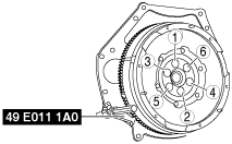
4. Hold the flywheel using the SST (49 E011 1A0).
am3uuw00008263
|
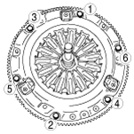
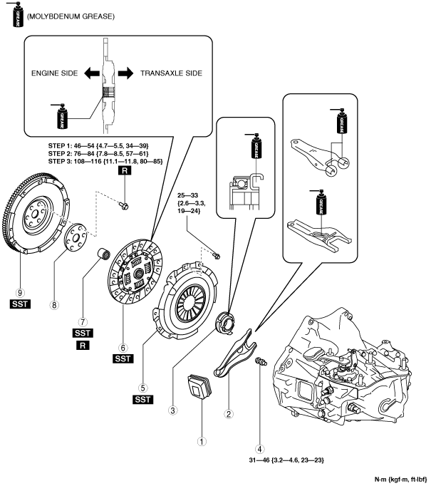
5. Tighten the lock bolts completely in the order shown in the figure in the following 3 steps.
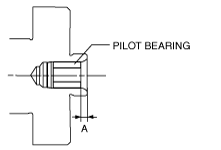
Pilot bearing installation note (SKYACTIV-G 1.5, SKYACTIV-G 2.0)
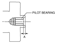
1. Install new pilot bearing to the specified position using the following tools.
am3uuw00002083
|
am3uuw00008265
|
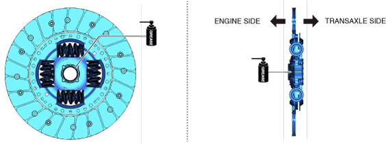
Clutch disc and clutch cover installation note (SKYACTIV-G 1.5, SKYACTIV-G 2.0)
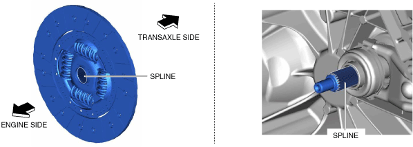
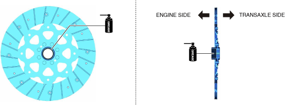
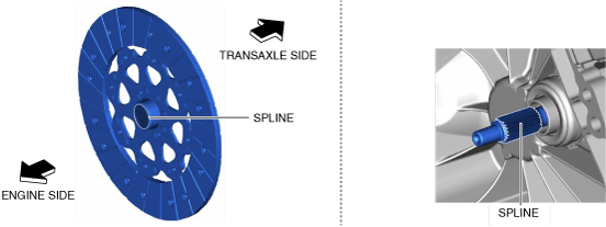
1. Apply grease to the spline (engine side) of the clutch disc.
am3uuw00015838
|
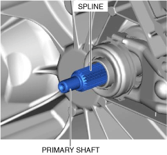
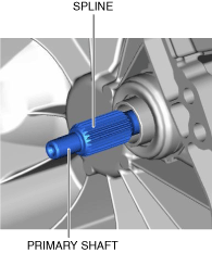
2. Insert the clutch disc into the primary shaft and wipe off the excess grease protruding from the spline.
am3uuw00015839
|
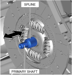
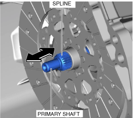
3. Slide the clutch disc three times in the directions of the arrows shown in the figure to engage to grease.
4. Remove the clutch disc from the primary shaft and wipe off the excess grease protruding from the spline.
am3uuw00015840
|
5. Verify that grease has been lightly applied to the clutch disc and the spline of the primary shaft.
am3uuw00015841
|
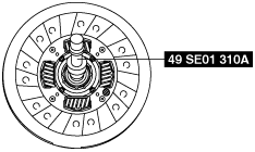
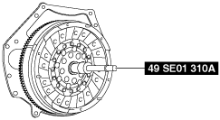
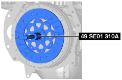
6. Hold the clutch disc position using the SST (49 SE01 310A).
am3uuw00002087
|
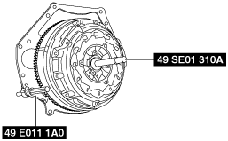
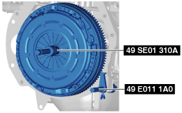
7. Hold the clutch unit using the SST (49 E011 1A0).
am3uuw00008266
|
8. Tighten the bolts in Min. 2 stages.
am3uuw00008267
|
9. Remove the SSTs (49 SE01 310A, 49 E011 1A0).
SKYACTIV-G 2.5
1. Disconnect the negative battery cable. (See NEGATIVE BATTERY CABLE DISCONNECTION/CONNECTION [SKYACTIV-G 1.5, SKYACTIV-G 2.0, SKYACTIV-G 2.5].)
2. Remove the manual transaxle. (See MANUAL TRANSAXLE REMOVAL/INSTALLATION [C66M-R (SKYACTIV-G 1.5, SKYACTIV-G 2.0, SKYACTIV-G 2.5)].)
3. Remove in the order indicated in the table.
4. Install in the reverse order of removal.
5. Add the specified amount of specified manual transaxle oil. (See MANUAL TRANSAXLE OIL REPLACEMENT [C66M-R].)
am3zzw00020876
|
|
1
|
Boot
|
|
2
|
Clutch release fork
|
|
3
|
Clutch release collar
|
|
4
|
Pivot pin
|
|
5
|
Clutch cover
|
|
6
|
Clutch disc
|
|
7
|
Pilot bearing
|
|
8
|
Dual-mass flywheel
|
Clutch cover and clutch disc removal note (SKYACTIV-G 2.5)
1. Install the SSTs (49 E011 1A0, 49 SE01 310A).
am6xuw00005861
|
2. Loosen each bolt one turn at a time in a crisscross pattern until spring tension is released.
3. Remove the clutch cover and clutch disc.
Pilot bearing removal note (SKYACTIV-G 2.5)
1. Use the SST (49 1285 071) to remove the pilot bearing.
am6xuw00005862
|
Dual-mass flywheel removal note (SKYACTIV-G 2.5)
1. Lock the dual-mass flywheel against rotation using the SST (49 E011 1A0).
am6xuw00006384
|
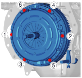
2. Loosen the lock bolts uniformly and gradually in the order shown in the figure, and remove them.
am6xuw00005863
|
3. Remove the dual-mass flywheel.
4. Inspect for oil leakage from the crankshaft rear oil seal.
Dual-mass flywheel installation note (SKYACTIV-G 2.5)
1. Clean the dual-mass flywheel.
2. Clean the crankshaft thread holes.
3. Install the dual-mass flywheel to the crankshaft.
4. Lock the dual-mass flywheel against rotation using the SST (49 E011 1A0).
am6xuw00006385
|
5. Temporarily tighten the new lock bolts.
6. Tighten the lock bolts completely in the order shown in the figure in the following 3 steps.
am6xuw00005868
|
Pilot bearing installation note (SKYACTIV-G 2.5)
1. Install new pilot bearing to the specified position using the following tools.
am6xuw00005869
|
am3uuw00008265
|
Clutch disc and clutch cover installation note (SKYACTIV-G 2.5)
1. Clean the splines of the new clutch disc and the primary shaft with a brush.
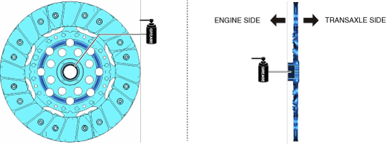
2. Apply grease to the spline (engine side) of the clutch disc.
am3zzw00020877
|
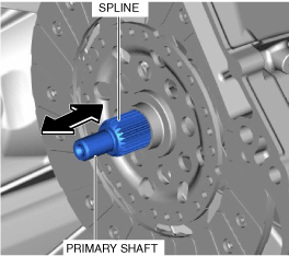
3. Insert the clutch disc into the primary shaft and wipe off the excess grease protruding from the spline.
am3zzw00020878
|
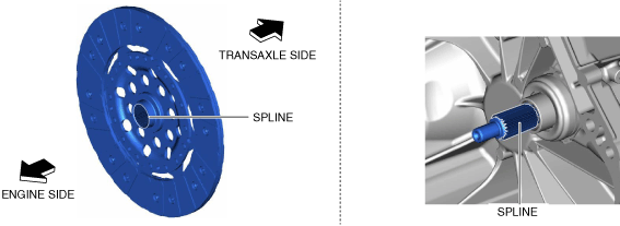
4. Slide the clutch disc three times in the directions of the arrows shown in the figure to engage to grease.
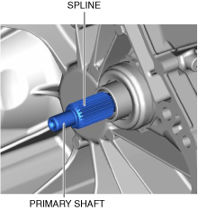
5. Remove the clutch disc from the primary shaft and wipe off the excess grease protruding from the spline.
am3zzw00020879
|
6. Verify that grease has been lightly applied to the clutch disc and the spline of the primary shaft.
am3zzw00020880
|
7. Hold the clutch disc position using the SST (49 SE01 310A).
am6xuw00006493
|
8. Install the new clutch cover while aligning the guide pins.
9. Install the SST (49 E011 1A0).
am6xuw00005871
|
10. Tighten the bolts uniformly and gradually in the order shown in the figure.
am6xuw00005872
|
11. Remove the SSTs (49 SE01 310A, 49 E011 1A0).
SKYACTIV-D 1.5
1. Disconnect the negative battery cable. (See NEGATIVE BATTERY CABLE DISCONNECTION/CONNECTION [SKYACTIV-D 1.5].)
2. Remove the manual transaxle. (See MANUAL TRANSAXLE REMOVAL/INSTALLATION [C66M-R (SKYACTIV-D 1.5)].)
3. Remove in the order indicated in the table.
4. Install in the reverse order of removal.
5. Add the specified amount of manual transaxle oil. (See MANUAL TRANSAXLE OIL REPLACEMENT [C66M-R].)
am3zzw00020881
|
|
1
|
Boot
|
|
2
|
Clutch release fork
|
|
3
|
Clutch release collar
|
|
4
|
Pivot pin
|
|
5
|
Clutch cover
|
|
6
|
Clutch disc
|
|
7
|
Pilot bearing
|
|
8
|
Dual-mass flywheel
|
Clutch cover and clutch disc removal note (SKYACTIV-D 1.5)
1. Hold the clutch unit using the SSTs (49 SE01 310A, 49 E011 1A0).
ac3wzw00001005
|
2. Loosen each bolt in small steps and diagonally.
3. Remove the clutch cover and clutch disc.
Pilot bearing removal note (SKYACTIV-D 1.5)
1. Use the SST (49 1285 071) to remove the pilot bearing.
ac3wzw00000997
|
Dual-mass flywheel removal note (SKYACTIV-D 1.5)
1. Hold the dual-mass flywheel using the SST (49 E011 1A0).
ac3wzw00001006
|
2. Remove the lock bolts, and remove the plate and the dual-mass flywheel.
3. Inspect for oil leakage from the crankshaft rear oil seal.
Dual-mass flywheel installation note (SKYACTIV-D 1.5)
1. Clean the dual-mass flywheel.
2. Clean the crankshaft thread holes.
3. Install the dual-mass flywheel to the crankshaft, and temporarily tighten a new lock bolts.
4. Hold the dual-mass flywheel using the SST (49 E011 1A0).
ac3wzw00001007
|
5. Tighten the lock bolts completely in the order shown in the figure in the following 3 steps.
Pilot bearing installation note (SKYACTIV-D 1.5)
1. Install new pilot bearing to the specified position using the following tools.
ac3wzw00001000
|
am2zzw00010010
|
Clutch disc and clutch cover installation note (SKYACTIV-D 1.5)
1. Apply grease to the spline (engine side) of the clutch disc.
am3zzw00020882
|
2. Insert the clutch disc into the primary shaft and wipe off the excess grease protruding from the spline.
am3zzw00020883
|
3. Slide the clutch disc three times in the directions of the arrows shown in the figure to engage to grease.
4. Remove the clutch disc from the primary shaft and wipe off the excess grease protruding from the spline.
am3zzw00020884
|
5. Verify that grease has been lightly applied to the clutch disc and the spline of the primary shaft.
am3zzw00020885
|
6. Hold the clutch disc position using the SST (49 SE01 310A).
ac3wzw00001008
|
7. Hold the clutch unit using the SST (49 E011 1A0).
ac3wzw00001009
|
8. Using the following procedure, install the clutch disc and clutch cover.
ac3wzw00001010
|
9. Remove the SSTs (49 SE01 310A, 49 E011 1A0).