ac5wzw00002839
|
MANUAL TRANSAXLE REMOVAL/INSTALLATION [C66M-R (SKYACTIV-G 1.5, SKYACTIV-G 2.0, SKYACTIV-G 2.5)]
id0515m81600mg
Removal
1. Disconnect the negative battery cable. (See NEGATIVE BATTERY CABLE DISCONNECTION/CONNECTION [SKYACTIV-G 1.5, SKYACTIV-G 2.0, SKYACTIV-G 2.5].)
2. Remove the plug hole plate. (See PLUG HOLE PLATE REMOVAL/INSTALLATION [SKYACTIV-G 1.5, SKYACTIV-G 2.0, SKYACTIV-G 2.5].)
3. Remove the front under cover No.2. (See FRONT UNDER COVER No.2 REMOVAL/INSTALLATION.)
4. Remove the front under cover No.1. (See FRONT UNDER COVER No.1 REMOVAL/INSTALLATION.)
5. Remove the splash shield. (See SPLASH SHIELD REMOVAL/INSTALLATION.)
6. Drain the manual transaxle oil. (See MANUAL TRANSAXLE OIL REPLACEMENT [C66M-R].)
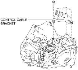
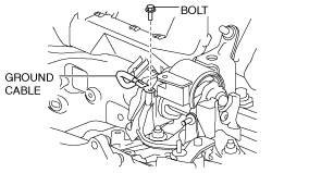
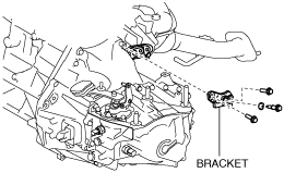
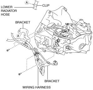
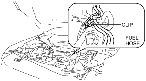
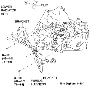
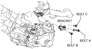
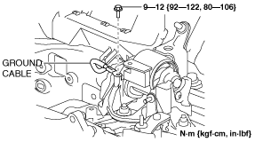
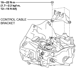
7. Disconnect and/or remove the following parts in the engine compartment.
ac5wzw00002839
|
am3zzw00017341
|
am6zzw00008393
|
ac5wzw00002841
|
8. Disconnect and/or remove the following parts related to the suspension and axle.
9. Disconnect and/or remove the following parts from the underside of the vehicle.
SKYACTIV-G 1.5
am3zzw00014234
|
SKYACTIV-G 2.0 (No.1 engine mount type A), SKYACTIV-G 2.5
am3uuw00010675
|
SKYACTIV-G 2.0 (No.1 engine mount type B)
ac5uuw00000735
|
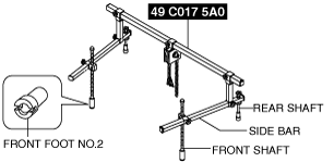
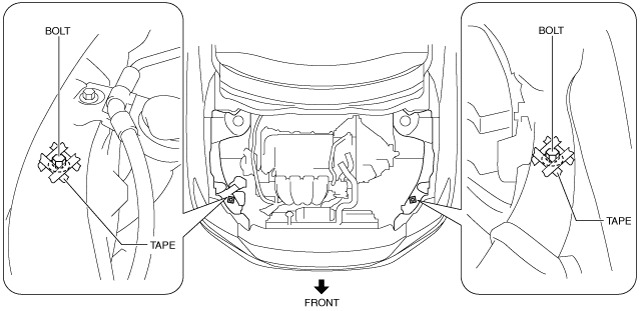
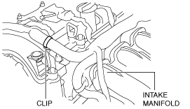
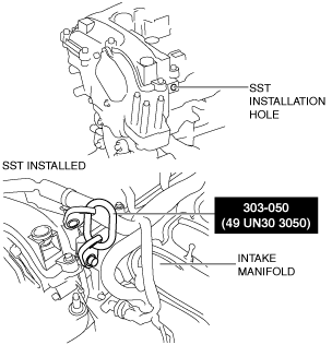
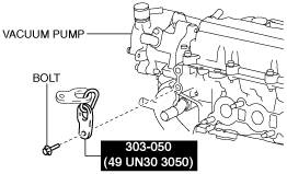
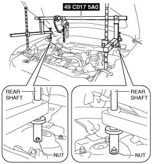
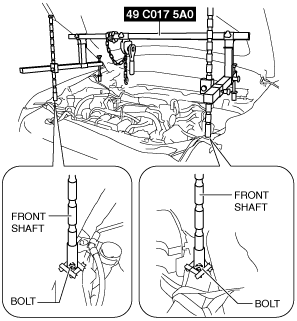
10. Install the SST using the following procedure.
am6zzw00010922
|
am6zzw00010817
|
am6zzw00010818
|
Engine front side
am6zzw00010819
|
Engine rear side
am6zzw00010820
|
am6zzw00008396
|
am6zzw00008397
|
am6zzw00008398
|
am6zzw00008399
|
am6zzw00008400
|
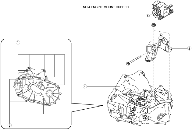
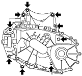
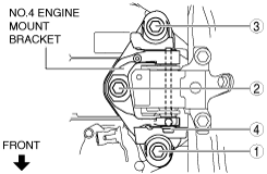
11. Remove in the order indicated in the table.
am6zzw00008401
|
|
1
|
Transaxle mounting bolt (upper side)
|
|
2
|
No.4 engine mount bracket
|
|
3
|
Transaxle mounting bolt (lower side)
|
|
4
|
MTX
|
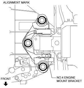
No.4 engine mount bracket removal note
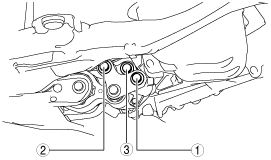
1. Place alignment marks on the locations shown in the figure so that they can be assembled to the same positions as before removal.
ac5uuw00000743
|
2. Remove the No.4 engine mount bracket.
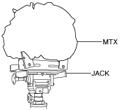
Transaxle mounting bolt removal note
1. Adjust the SST and lean the engine toward the MTX.
am6zzw00008399
|
2. Support the MTX on a jack.
am6zzw00008402
|
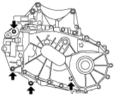
3. Remove the transaxle mounting bolts (lower side).
ac5uuw00000745
|
4. Remove the MTX.
Installation
1. Set the MTX on a jack and lift into place.
am6zzw00008402
|
2. Install the MTX to the engine, and tighten the transaxle mounting bolts.
am3uuw00008227
|
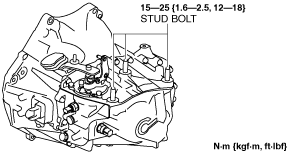
3. Tighten the stud bolts for the MTX.
ac5wzw00002845
|
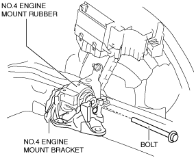
4. Install the No.4 engine mount bracket to No.4 engine mount rubber, and temporarily tighten the installation bolt.
ac5uuw00000747
|
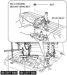
5. Pull up the MTX using the SSTs, pass the MTX stud bolts through the No.4 engine mount bracket, and temporarily tighten the No.4 engine mount installation nuts.
am6zzw00008403
|
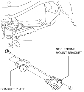
6. Install the No.1 engine mount bracket and bracket plate to the MTX, and temporarily tighten the installation bolts.
SKYACTIV-G 1.5
am3zzw00014234
|
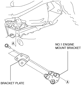
SKYACTIV-G 2.0 (No.1 engine mount type A), SKYACTIV-G 2.5
am3uuw00010675
|
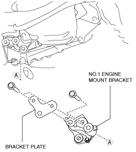
SKYACTIV-G 2.0 (No.1 engine mount type B)
ac5uuw00000735
|
7. Install the front crossmember component and No.1 engine mount rubber as a single unit. (See FRONT CROSSMEMBER REMOVAL/INSTALLATION [SKYACTIV-G 1.5, SKYACTIV-G 2.0, SKYACTIV-G 2.5].)
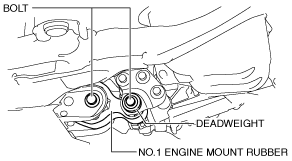
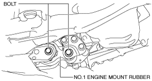
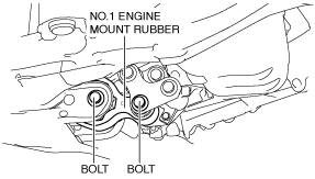
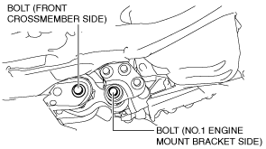
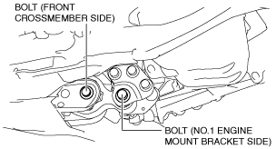
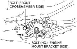
8. Temporarily tighten the No.1 engine mount rubber installation bolts.
SKYACTIV-G 1.5
am3zzw00014235
|
SKYACTIV-G 2.0 (No.1 engine mount type A), SKYACTIV-G 2.5
am3uuw00010677
|
SKYACTIV-G 2.0 (No.1 engine mount type B)
am3uuw00012908
|
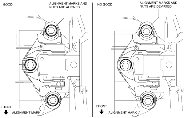
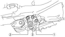
9. Align the alignment marks on the No.4 engine mount bracket and nuts, and temporarily tighten the nuts shown in the figure.
am3zzw00014236
|
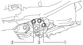
10. Tighten the No.4 engine mount bracket installation nuts and bolt in the order shown in the figure.
ac5uuw00000751
|
|
No. |
Tightening torque |
|---|---|
|
1, 2, 3
|
92—116 N·m {9.4—11 kgf·m, 68—85 ft·lbf}
|
|
4
|
81—99 N·m {8.3—10 kgf·m, 60—73 ft·lbf}
|
11. Tighten the No.1 engine mount bracket and bracket plate installation bolts in the order shown in the figure.
SKYACTIV-G 1.5
am3zzw00014237
|
SKYACTIV-G 2.0 (No.1 engine mount type A), SKYACTIV-G 2.5
am3uuw00010679
|
SKYACTIV-G 2.0 (No.1 engine mount type B)
am3zzw00016024
|
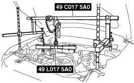
12. Remove the SSTs (49 C017 5A0, 49 L017 5A0).
13. Tighten the No.1 engine mount rubber installation bolts.
SKYACTIV-G 1.5
am3zzw00014238
|
Tightening torque
|
Installation position |
Tightening torque |
|---|---|
|
No.1 engine mount bracket side
|
130—142 N·m {13.3—14.4 kgf·m, 96—104 ft·lbf}
|
|
Front crossmember side
|
130—164 N·m {14—16 kgf·m, 96—120 ft·lbf}
|
SKYACTIV-G 2.0 (No.1 engine mount type A), SKYACTIV-G 2.5
am3zzw00014597
|
Tightening torque
|
Installation position |
Tightening torque |
|---|---|
|
No.1 engine mount bracket side
|
140—163 N·m {15—16 kgf·m, 104—120 ft·lbf}
|
|
Front crossmember side
|
130—164 N·m {14—16 kgf·m, 96—120 ft·lbf}
|
SKYACTIV-G 2.0 (No.1 engine mount type B)
am3zzw00016025
|
Tightening torque
|
Installation position |
Tightening torque |
|---|---|
|
No.1 engine mount bracket side
|
140—163 N·m {15—16 kgf·m, 104—120 ft·lbf}
|
|
Front crossmember side
|
130—164 N·m {14—16 kgf·m, 96—120 ft·lbf}
|
14. Connect and/or Install the following parts to the underside of the vehicle.
15. Connect and/or Install the following parts related to the suspension and axle.
16. Connect and/or install the following parts in the engine compartment.
am6zzw00008398
|
am6zzw00010818
|
ac5wzw00002846
|
am6zzw00008406
|
am3zzw00016026
|
ac5wzw00002847
|
17. Install the splash shield. (See SPLASH SHIELD REMOVAL/INSTALLATION.)
18. Install the front under cover No.1. (See FRONT UNDER COVER No.1 REMOVAL/INSTALLATION.)
19. Add the specified amount of specified manual transaxle oil. (See MANUAL TRANSAXLE OIL REPLACEMENT [C66M-R].)
20. Install the front under cover No.2. (See FRONT UNDER COVER No.2 REMOVAL/INSTALLATION.)
21. Connect the negative battery cable. (See NEGATIVE BATTERY CABLE DISCONNECTION/CONNECTION [SKYACTIV-G 1.5, SKYACTIV-G 2.0, SKYACTIV-G 2.5].)
22. Install the plug hole plate. (See PLUG HOLE PLATE REMOVAL/INSTALLATION [SKYACTIV-G 1.5, SKYACTIV-G 2.0, SKYACTIV-G 2.5].)
23. If the MTX is overhauled, perform the “INSPECTION AFTER MANUAL TRANSAXLE OVERHAUL”. (See INSPECTION AFTER MANUAL TRANSAXLE OVERHAUL [C66M-R].)