am2zzw00003836
|
MECHANICAL SYSTEM TEST [FN4A-EL]
id051701290600
Mechanical System Test Preparation
1. Engage the parking brake and use wheel chocks at the front and rear of the wheels.
2. Inspect the engine coolant. (See ENGINE COOLANT LEVEL INSPECTION [MZR 1.6].)
3. Inspect the engine oil. (See ENGINE OIL LEVEL INSPECTION [MZR 1.6].)
4. Inspect the ATF. (See AUTOMATIC TRANSAXLE FLUID (ATF) INSPECTION [FN4A-EL].)
5. Inspect the idle speed. (See ENGINE TUNE-UP [MZR 1.6].)
6. Inspect the ignition timing. (See ENGINE TUNE-UP [MZR 1.6].)
7. Verify that no DTCs recorded. (See ON-BOARD DIAGNOSTIC SYSTEM DTC INSPECTION [FN4A-EL].)
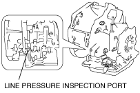
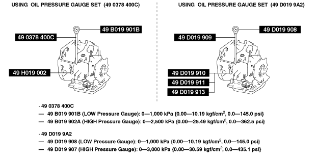
Line Pressure Test
1. Perform “Mechanical System Test Preparation”. (See Mechanical System Test Preparation.)
2. Perform the line pressure test with the engine idle at D position.
am2zzw00003836
|
am3zzw00008937
|
3. Perform the line pressure test at the engine idle at each position in the same manner.
4. Stop the engine.
5. Perform the line pressure test with the engine stall at D position.
am3zzw00008938
|
6. Perform the line pressure test with the engine stall at each position in the same manner.
|
Condition |
Possible Cause |
|
|---|---|---|
|
Low pressure
|
In all positions
|
• Worn oil pump
• Oil leakage from oil pump, control valve body, and/or transaxle case
• Pressure regulator valve sticking
• Pressure control solenoid malfunction
|
|
In D, M (1GR, 2GR) position
|
• Oil leakage from forward clutch hydraulic circuit
|
|
|
In M (2GR) position
|
• Oil leakage from 2-4 brake band hydraulic circuit
|
|
|
In M (1GR), R position
|
• Oil leakage from low and reverse brake hydraulic circuit
|
|
|
In R position
|
• Oil leakage from reverse clutch hydraulic circuit
|
|
|
High pressure
|
In all positions
|
• Pressure regulator valve stuck
• Pressure control solenoid malfunction
|
Line Pressure
|
Test Condition |
Specification (kPa {kgf/cm2, psi}) |
|
|---|---|---|
|
Idle
|
D position
|
330—470 {3.37—4.79, 47.9—68.1}
|
|
M (1GR, 2GR) position
|
330—470 {3.37—4.79, 47.9—68.1}
|
|
|
R position
|
490—710 {5.00—7.23, 71.1—102.0}
|
|
|
Stall
|
D position
|
1,080—1,270 {11.02—12.95, 156.7—184.1}
|
|
M (1GR, 2GR) position
|
1,080—1,270 {11.02—12.95, 156.7—184.1}
|
|
|
R position
|
1,500—1,720 {15.30—17.53, 217.6—249.4}
|
|
7. Stop the engine.
8. Remove the SSTs.
9. Install a new square-head plug in the inspection port.
Stall Test
1. Perform “Mechanical System Test Preparation”. (See Mechanical System Test Preparation.)
2. Start the engine.
3. Perform the stall test at D position.
4. Perform the stall test at each position in the same manner.
|
Condition |
Possible Cause |
||
|---|---|---|---|
|
Above specification
|
In all positions
|
Insufficient line pressure
|
• Worn oil pump
• Oil leakage from oil pump, control valve body, and/or transaxle case
• Pressure regulator valve sticking
• Converter relief valve sticking
• Pressure control solenoid malfunction
|
|
In D, M (1GR, 2GR) position
|
• Forward clutch slipping
|
||
|
In D position
|
• One-way clutch malfunction
|
||
|
In D, M (2GR) position
|
• 2-4 brake band slipping
• One-way clutch malfunction
|
||
|
In D, M (1GR) position
|
• Low and reverse brake slipping
• One-way clutch malfunction
|
||
|
In R position
|
• Perform “ROAD TEST” to determine whether problem is in reverse clutch or low and reverse brake
|
||
|
Below specification
|
• Engine lack of power
|
||
Stall Speed
|
Test Condition |
Specification (rpm) |
|---|---|
|
D position
|
2,100—2,700
|
|
M position
|
2,100—2,700
|
|
R position
|
2,100—2,700
|
Time Lag Test
1. Perform “Mechanical System Test Preparation”. (See Mechanical System Test Preparation.)
2. Start the engine.
3. Perform the time lag test when selecting the selector lever from N position to D position.
4. Perform the time lag test when selecting the selector lever from N position to R position in the same manner.
|
Condition |
Possible Cause |
|
|---|---|---|
|
From N position to D position
|
More than specification
|
• Low line pressure
• Oil leakage from forward clutch hydraulic circuit
• Forward clutch slipping
• Shift solenoid A malfunction
|
|
Less than specification
|
• High line pressure
• Shift solenoid A malfunction
• Forward accumulator malfunction
|
|
|
From N position to R position
|
More than specification
|
• Low line pressure
• Low and reverse brake slipping
• Reverse clutch slipping
|
|
Less than specification
|
• High line pressure
• Servo apply accumulator malfunction
• Shift solenoid B malfunction
|
|
Time Lag
|
Test Condition |
Specification (s) |
|---|---|
|
From N position to D position
|
0.4—0.7
|
|
From N position to R position
|
0.4—0.7
|