 |
am3zzw00007382
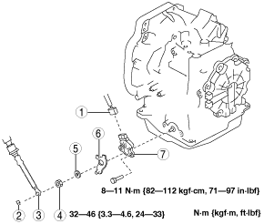
TRANSAXLE RANGE (TR) SWITCH REMOVAL/INSTALLATION [FN4A-EL]
id051701292000
1. Select the selector lever to N position.
2. Perform the following procedures.
3. Remove in the order indicated in the table.
am3zzw00007382
|
|
1
|
Connector
|
|
2
|
Clip
|
|
3
|
Selector cable
|
|
4
|
Manual shaft nut
|
|
5
|
Washer
|
|
6
|
Manual shaft lever
|
|
7
|
TR switch
(See TR switch Installation Note.)
|
4. Install in the reverse order of removal.
5. Inspect the TR switch. (See TRANSAXLE RANGE (TR) SWITCH INSPECTION [FN4A-EL].)
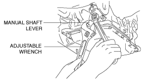
Manual Shaft Nut Removal Note
1. Set the adjustable wrench as shown to hold the manual shaft lever and loosen the manual shaft nut.
am6xuw00001948
|
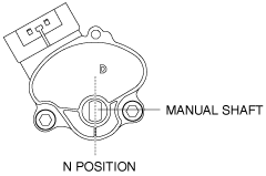
TR switch Installation Note
1. Verify that the manual shaft is aligned with N position.
am3uuw00002410
|
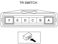
2. Adjust the TR switch between terminals B and C until the resistance becomes specification.
am3uuw00002411
|
3. Tighten the TR switch installation bolts.
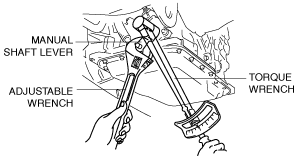
Manual Shaft Nut Installation Note
1. Set the adjustable wrench as shown to hold the manual shaft lever and tighten the manual shaft nut.
am6xuw00001950
|