|
1
|
INSPECT SOLAR RADIATION SENSOR CONNECTOR
• Switch the ignition off.
• Disconnect the negative battery cable.
• Disconnect the solar radiation sensor connector.
• Inspect the connector and terminals (corrosion, damage, pin disconnection).
• Are the connector and terminals normal?
|
Yes
|
Go to the next step.
|
|
No
|
Repair/replace the connector or terminal.
After repair procedure, go to the next step.
|
|
2
|
INSPECT SOLAR RADIATION SENSOR
• Inspect the solar radiation sensor.
• Is it normal?
|
Yes
|
Go to the next step.
|
|
No
|
Replace the solar radiation sensor.
Go to the next step.
|
|
3
|
INSPECT SOLAR RADIATION SENSOR CIRCUIT FOR OPEN CIRCUIT
• Disconnect the climate control unit connector.
• Disconnect the solar radiation sensor connector.
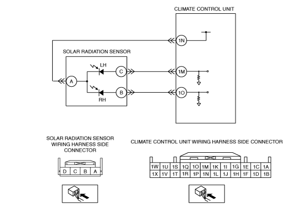
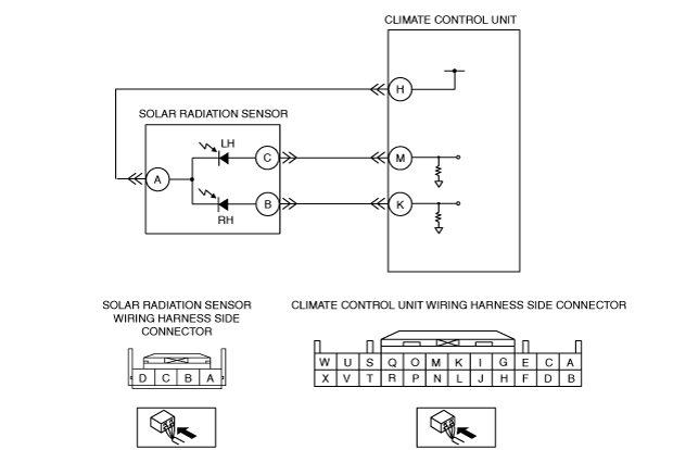
• Inspect for continuity between the following terminals (wiring harness-side):
-
― Climate control unit terminal H—solar radiation sensor terminal A
― Climate control unit terminal M—solar radiation sensor terminal C
― Climate control unit terminal K—solar radiation sensor terminal B
• Is there continuity?
|
Yes
|
Go to the next step.
|
|
No
|
Refer to the wiring diagram and verify whether or not there is a common connector between climate control unit terminal and solar radiation sensor terminal.
If there is a common connector:
• Determine the malfunctioning part by inspecting the common connector and the terminal for corrosion, damage, or pin disconnection, and the common wiring harness for an open circuit.
• Repair or replace the malfunctioning part.
If there is no common connector:
• Repair or replace the wiring harness which has an open circuit.
Go to the next step.
|
|
4
|
INSPECT SOLAR RADIATION SENSOR CIRCUIT FOR SHORT TO POWER SUPPLY
• Connect the negative battery cable.
• Switch the ignition ON (engine off or on).
• Measure the voltage at the following terminals (wiring harness-side):
-
― Climate control unit terminal H
― Climate control unit terminal M
― Climate control unit terminal K
• Is the voltage 0 V?
|
Yes
|
Go to the next step.
|
|
No
|
Refer to the wiring diagram and verify whether or not there is a common connector between climate control unit terminal and solar radiation sensor terminal.
If there is a common connector:
• Determine the malfunctioning part by inspecting the common connector and the terminal for corrosion, damage, or pin disconnection, and the common wiring harness for a short to power supply.
• Repair or replace the malfunctioning part.
If there is no common connector:
• Repair or replace the wiring harness which has a short to power supply.
Go to the next step.
|
|
5
|
VERIFY CLIMATE CONTROL UNIT CONNECTOR CONDITION
• Switch the ignition off.
• Disconnect the negative battery cable.
• Inspect the connector and terminals (corrosion, damage, pin disconnection).
• Are the connector and terminals normal?
|
Yes
|
Go to the next step.
|
|
No
|
Repair/replace the malfunctioning vehicle wiring harness, connector, or terminal.
After repair procedure, go to the next step.
|
|
6
|
VERIFY THAT SAME DTC IS NOT OUTPUT AGAIN
• Reconnect the disconnected connectors.
• Connect the negative battery cable.
• Clear the past malfunction from memory.
• Is DTC B1A63:12, B1A63:13, B1A64:12 or B1A64:13 output?
|
Yes
|
Repeat the inspection from Step 1.
• If the malfunction does not recur, go to the next step.
• If the malfunction recurs, replace the climate control unit.
Go to the next step.
|
|
No
|
Go to the next step.
|
|
7
|
VERIFY THAT NO OTHER DTCs ARE PRESENT
• Verify other DTCs displayed.
• Are any other DTCs output?
|
Yes
|
Perform the corresponding DTC inspection.
|
|
No
|
DTC troubleshooting completed.
|