 |
ac5wzw00002768
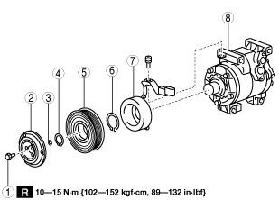
MAGNETIC CLUTCH DISASSEMBLY/ASSEMBLY [SKYACTIV-D 2.2]
id0711000063k5
Magnetic Clutch is Disassembled/Assembled with A/C Compressor Removed from Vehicle
1. Disconnect the negative battery cable. (See NEGATIVE BATTERY CABLE DISCONNECTION/CONNECTION [SKYACTIV-D 2.2].)
2. Discharge the refrigerant. (See REFRIGERANT CHARGING.)
3. Remove the front under cover No.2. (See FRONT UNDER COVER No.2 REMOVAL/INSTALLATION.)
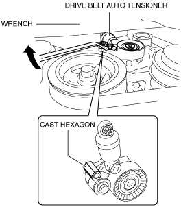
4. Remove the drive belt. (See DRIVE BELT REMOVAL/INSTALLATION [SKYACTIV-D 2.2].)
5. Remove the A/C compressor. (See A/C COMPRESSOR REMOVAL/INSTALLATION [SKYACTIV-D 2.2].)
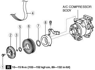
6. Disassemble in the order indicated in the table.
ac5wzw00002768
|
|
1
|
Bolt
|
|
2
|
Pressure plate
|
|
3
|
Shim
|
|
4
|
Snap ring
|
|
5
|
A/C compressor pulley
|
|
6
|
Snap ring
|
|
7
|
Stator
|
|
8
|
A/C compressor body
|
7. Assemble in the reverse order of disassembly.
8. Adjust the magnetic clutch clearance. (See MAGNETIC CLUTCH ADJUSTMENT [SKYACTIV-D 2.2].)
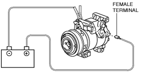
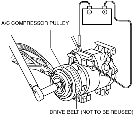
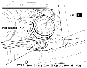
Bolt removal/installation note
1. When removing or installing the bolt, lock the A/C compressor pulley against rotation using the following procedure.
ac5wzw00001840
|
ac5wzw00001841
|
2. When installing a new A/C compressor body, replace the recommended bolt.
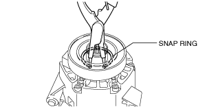
Snap ring removal/installation note
1. Remove/install the snap ring using a snap ring pliers.
am3zzw00010999
|
Magnetic Clutch is Disassembled/Assembled with A/C Compressor Equipped to Vehicle
1. Remove the front tire (RH). (See GENERAL PROCEDURES (FRONT AND REAR AXLES).)
2. Remove the front splash shield No.1 (RH). (See SPLASH SHIELD REMOVAL/INSTALLATION.)
3. Bend back the front side of the mudguard (RH). (See MUDGUARD REMOVAL/INSTALLATION.)
4. Remove the front under cover No.2. (See FRONT UNDER COVER No.2 REMOVAL/INSTALLATION.)
5. Disassemble in the order indicated in the table.
am6xuw00006119
|
|
1
|
Bolt
|
|
2
|
Pressure plate
|
|
3
|
Shim
|
|
4
|
Drive belt
|
|
5
|
Snap ring
|
|
6
|
A/C compressor pulley
|
|
7
|
Snap ring
|
|
8
|
Stator
|
6. Assemble in the reverse order of disassembly.
7. Adjust the magnetic clutch clearance. (See MAGNETIC CLUTCH ADJUSTMENT [SKYACTIV-D 2.2].)
Bolt removal/installation note
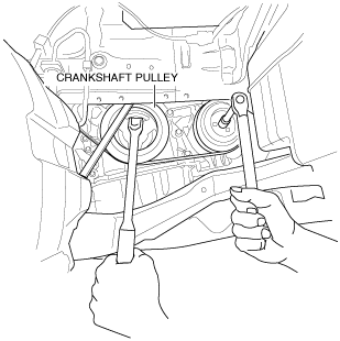
1. When removing or installing the bolt, lock the A/C compressor pulley against rotation using the following procedure.
2. Secure the crankshaft pulley.
am6xuw00006120
|
3. Remove the bolt with the pressure plate secured.
am6xuw00006121
|
am6xuw00006122
|
4. Turn the A/C relay off using the "ACCS" simulation function.
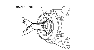
Snap ring removal/installation note
1. Remove/install the snap ring using a snap ring pliers.
am6xuw00006123
|
Stator removal/installation note
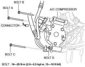
1. Disconnect the negative battery cable. (See NEGATIVE BATTERY CABLE DISCONNECTION/CONNECTION [SKYACTIV-D 2.2].)
2. Disconnect the magnetic clutch connector.
am6xuw00006125
|
3. Remove the bolts A, B and C.
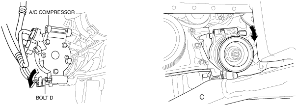
4. Loose bolt D approx. 2 mm {0.08 in}.
5. Tilt the A/C compressor centered around bolt D.
am6xuw00006126
|
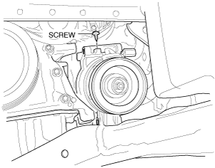
6. Remove the screw.
am6xuw00006127
|
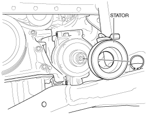
7. Remove the stator.
am6xuw00006128
|