 |
ac5uuw00001202
AIR MIX ACTUATOR INSPECTION [FULL-AUTO AIR CONDITIONER]
id0740a1802500
L.H.D.
Driver-side (With Dual Type Climate Control Unit)
1. Disconnect the negative battery cable. (See NEGATIVE BATTERY CABLE DISCONNECTION/CONNECTION [SKYACTIV-D 2.2].)(See NEGATIVE BATTERY CABLE DISCONNECTION/CONNECTION [SKYACTIV-G 1.5, SKYACTIV-G 2.0, SKYACTIV-G 2.5].)(See NEGATIVE BATTERY CABLE DISCONNECTION/CONNECTION [MZR 1.6].)(See NEGATIVE BATTERY CABLE DISCONNECTION/CONNECTION [SKYACTIV-D 1.5].)
2. Remove the following parts:
3. Remove the driver-side air mix actuator. (See AIR MIX ACTUATOR REMOVAL/INSTALLATION [FULL-AUTO AIR CONDITIONER].)
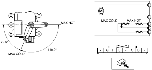
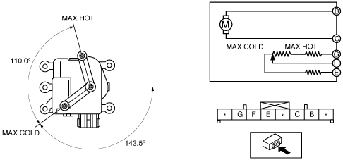
4. Apply battery positive voltage and connect the ground to the air mix actuator terminals as indicated in the table below and verify the operation condition.
|
B+ Terminal |
Ground Terminal |
Operation |
|---|---|---|
|
B
|
C
|
COLD → HOT
|
|
C
|
B
|
HOT → COLD
|
ac5uuw00001202
|
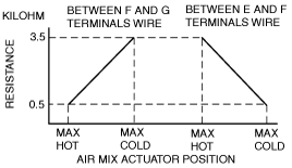
5. Verify that the resistance between terminals F and G, E and F matches the air mix actuator operation as shown in the graph.
am3uuw00004047
|
Passenger-side
1. Disconnect the negative battery cable. (See NEGATIVE BATTERY CABLE DISCONNECTION/CONNECTION [SKYACTIV-D 2.2].)(See NEGATIVE BATTERY CABLE DISCONNECTION/CONNECTION [SKYACTIV-G 1.5, SKYACTIV-G 2.0, SKYACTIV-G 2.5].)(See NEGATIVE BATTERY CABLE DISCONNECTION/CONNECTION [MZR 1.6].)(See NEGATIVE BATTERY CABLE DISCONNECTION/CONNECTION [SKYACTIV-D 1.5].)
2. Remove the following parts:
3. Remove the passenger-side air mix actuator. (See AIR MIX ACTUATOR REMOVAL/INSTALLATION [FULL-AUTO AIR CONDITIONER].)
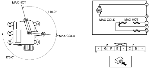
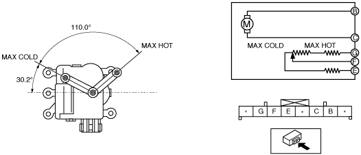
4. Apply battery positive voltage and connect the ground to the air mix actuator terminals as indicated in the table below and verify the operation condition.
|
B+ Terminal |
Ground Terminal |
Operation |
|---|---|---|
|
B
|
C
|
HOT → COLD
|
|
C
|
B
|
COLD → HOT
|
ac5uuw00001203
|
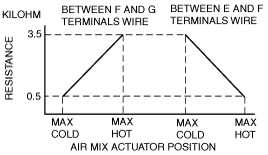
5. Verify that the resistance between terminals F and G, E and F matches the air mix actuator operation as shown in the graph.
am3uuw00004049
|
R.H.D.
Driver-side (With Dual Type Climate Control Unit)
1. Disconnect the negative battery cable. (See NEGATIVE BATTERY CABLE DISCONNECTION/CONNECTION [SKYACTIV-D 2.2].)(See NEGATIVE BATTERY CABLE DISCONNECTION/CONNECTION [SKYACTIV-G 1.5, SKYACTIV-G 2.0, SKYACTIV-G 2.5].)(See NEGATIVE BATTERY CABLE DISCONNECTION/CONNECTION [SKYACTIV-D 1.5].)
2. Remove the following parts:
3. Remove the driver-side air mix actuator. (See AIR MIX ACTUATOR REMOVAL/INSTALLATION [FULL-AUTO AIR CONDITIONER].)
4. Apply battery positive voltage and connect the ground to the air mix actuator terminals as indicated in the table below and verify the operation condition.
|
B+ Terminal |
Ground Terminal |
Operation |
|---|---|---|
|
B
|
C
|
HOT → COLD
|
|
C
|
B
|
COLD → HOT
|
am3zzw00015124
|
5. Verify that the resistance between terminals F and G, E and F matches the air mix actuator operation as shown in the graph.
am3zzw00015125
|
Passenger-side
1. Disconnect the negative battery cable. (See NEGATIVE BATTERY CABLE DISCONNECTION/CONNECTION [SKYACTIV-D 2.2].)(See NEGATIVE BATTERY CABLE DISCONNECTION/CONNECTION [SKYACTIV-G 1.5, SKYACTIV-G 2.0, SKYACTIV-G 2.5].)(See NEGATIVE BATTERY CABLE DISCONNECTION/CONNECTION [SKYACTIV-D 1.5].)
2. Remove the following parts:
3. Remove the passenger-side air mix actuator. (See AIR MIX ACTUATOR REMOVAL/INSTALLATION [FULL-AUTO AIR CONDITIONER].)
4. Apply battery positive voltage and connect the ground to the air mix actuator terminals as indicated in the table below and verify the operation condition.
|
B+ Terminal |
Ground Terminal |
Operation |
|---|---|---|
|
B
|
C
|
COLD → HOT
|
|
C
|
B
|
HOT → COLD
|
am3zzw00015126
|
5. Verify that the resistance between terminals F and G, E and F matches the air mix actuator operation as shown in the graph.
am3zzw00015127
|