 |
am3uuw00012297
DTC INSPECTION
id080200080500
CMDTC Self Test
1. Connect the M-MDS to the DLC-2.
2. After the vehicle is identified, select the following items from the initialization screen of the M-MDS.
3. Verify the DTC according to the directions on the screen.
4. After completion of repairs, clear all DTCs stored in the SAS control module. (See CLEARING DTC.)
ODDTC Self Test
1. Connect the M-MDS to the DLC-2.
2. After the vehicle is identified, select the following items from the initialization screen of the M-MDS.
3. Verify the DTC according to the directions on the screen.
4. After completion of repairs, clear all DTCs stored in the SAS control module. (See CLEARING DTC.)
Snapshot Data Table
|
Snapshot data item |
Unit |
Definition |
Data read/use method |
Corresponding PID data monitor item |
|
|---|---|---|---|---|---|
|
AAT
|
°C
|
°F
|
Ambient temperature
|
—
|
—
|
|
APP_STATUS
|
Accelerator Pedal Off/
Under20%/
Over20%/
FAIL
|
Accelerator pedal position status
|
—
|
—
|
|
|
CFG_STATUS
|
Config Complete/
Not Configured/
Config Error
|
Instrument cluster configuration status
|
—
|
—
|
|
|
ECT_STATUS
|
Under 0 degrees C/
0-Under 80 degrees C/
Over 80 degrees C/
FAIL
|
Engine coolant temperature status
|
—
|
—
|
|
|
FAULT_CNT
|
—
|
Number of malfunction detections
|
—
|
—
|
|
|
FIRST_DET_IG
|
hh:mm:ss*1
|
Time when initial malfunction occurs (IG-ON counter)
• Elapsed time from when ignition is switched ON (engine off or on) until SAS control module detects first malfunction*3
|
—
|
—
|
|
|
IC_VPWR
|
V
|
Instrument cluster power supply voltage
|
• The SAS control module constantly receives the power supply voltage value of the instrument cluster sent via CAN signal from the instrument cluster.
• If a DTC is detected, the SAS control module records the power supply voltage of the instrument cluster when the DTC was detected, and it is displayed in the M-MDS.
|
VPWR*2
|
|
|
IG-ON_TIMER
|
hh:mm:ss*1
|
Elapsed time since ignition was switched ON (engine off or on)
|
• The SAS control module constantly receives the elapsed time since the ignition was switched ON (engine off or on) sent via CAN signal from the instrument cluster.
• If a DTC is detected, the SAS control module records the elapsed time since the ignition was switched ON (engine off or on) when the DTC was detected, and it is displayed in the M-MDS.
|
—
|
|
|
LAST_CLR
|
hh:mm:ss*1
|
Repair time for last malfunction (B+ counter)
• Elapsed time from when battery is connected until SAS control module detects that last malfunction is repaired*3
|
—
|
—
|
|
|
LAST_CLR_IG
|
hh:mm:ss*1
|
Repair time for last malfunction (IG-ON counter)
• Elapsed time from when ignition is switched ON (engine off or on) until SAS control module detects that last malfunction is repaired*3
|
—
|
—
|
|
|
LAST_DET
|
hh:mm:ss*1
|
Time when last malfunction occurs (B+ counter)
• Elapsed time from when battery is connected until SAS control module detects last malfunction*3
|
—
|
—
|
|
|
LAST_DET_IG
|
hh:mm:ss*1
|
Time when last malfunction occurs (IG-ON counter)
• Elapsed time from when ignition is switched ON (engine off or on) until SAS control module detects last malfunction*3
|
—
|
—
|
|
|
PWR_MODE_KEY
|
Key Out/
Key Recently Out (Position 0)/
Accessory (Position 1)/
Post Ignition (Position 2)/
Ignition On (Position 2)/
Running (Position 2)/
Running - Starting
|
• Key Out: Ignition switched off
• Key Recently Out (Position 0): Elapsed time within 3 s since ignition was switched off
• Accessory (Position 1): Ignition is switched to ACC
• Post Ignition (Position 2): Elapsed time within 3 s since ignition was switched ON (engine off or on)
• Ignition On (Position 2): Ignition switched ON (engine off)
• Running (Position 2): Ignition switched ON (engine on)
• Running - Starting: Cranking condition
|
• The SAS control module constantly receives the ignition switch status sent via CAN signal from the instrument cluster.
• If a DTC is detected, the SAS control module records the ignition switch status when the DTC was detected, and it is displayed in the M-MDS.
|
—
|
|
|
RPM_STATUS
|
Engine Stop/
Under1500rpm/
Over1500rpm/
FAIL
|
Engine speed status
|
• The SAS control module constantly receives the engine speed sent via CAN signal from the instrument cluster.
• If a DTC is detected, the SAS control module records the engine speed when the DTC was detected, and it is displayed in the M-MDS.
|
TACHOMTR*2
|
|
|
SHIFT_STATUS
|
P/N/
D/
R/
FAIL
|
Selector lever position status
|
• The SAS control module constantly receives the selector lever position sent via CAN signal from the instrument cluster.
• If a DTC is detected, the SAS control module records the selector lever position when the DTC was detected, and it is displayed in the M-MDS.
|
—
|
|
|
TOTAL_DIST
|
km
|
miles
|
Accumulated total traveled distance from completion of vehicle until SAS control module detects DTC (Odometer value in instrument cluster)
|
The total traveled distance from which the SAS control module detects DTCs to the present can be calculated by performing the following procedure.
1. Verify the odometer value in the instrument cluster.
2. Verify the snapshot data item TOTAL_DIST.
3. Subtract 2 from 1.
|
—
|
|
TOTAL_TIME
|
hh:mm:ss*1
|
Accumulated total elapsed time since vehicle completion until SAS control module detects a DTC*3
|
The elapsed time from which the SAS control module detects DTCs to the present can be calculated by performing the following procedure.
1. Verify the instrument cluster PID item TOTAL_TIME.
2. Verify the snapshot data item TOTAL_TIME.
3. Subtract 2 from 1.
|
TOTAL_TIME*2
|
|
|
VPWR
|
V
|
SAS control module power supply malfunction
|
—
|
VPWR_IGA
|
|
|
VSPD_STATUS
|
Stop/
0-10km/h/
Over10km/h/
FAIL
|
Vehicle speed status
|
• The SAS control module constantly receives the vehicle speed sent via CAN signal from the instrument cluster.
• If a DTC is detected, the SAS control module records the vehicle speed when the DTC was detected, and it is displayed in the M-MDS.
|
SPEEDOMTR*2
|
|
am3uuw00012297
|
|
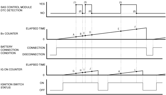
SAS control module DTC detection period |
Snapshot data |
||||||
|---|---|---|---|---|---|---|---|
|
FAULT_CNT (Number of malfunction detections) |
TOTAL_TIME |
FIRST_DET_IG |
LAST_DET |
LAST_DET_IG |
LAST_CLR |
LAST_CLR_IG |
|
|
Number of malfunction detections |
Time when first malfunction occurs (B+ counter) |
Time when initial malfunction occurs (IG-ON counter) |
Time when last malfunction occurs (B+ counter) |
Time when last malfunction occurs (IG-ON counter) |
Repair time for last malfunction (B+ counter) |
Repair time for last malfunction (IG-ON counter) |
|
|
(1)
|
1
|
A
|
G
|
A
|
G
|
-
|
-
|
|
(2)
|
1
|
A
|
G
|
A
|
G
|
B
|
H
|
|
(3)
|
2
|
A
|
G
|
C
|
I
|
B
|
H
|
|
(4)
|
2
|
A
|
G
|
C
|
I
|
D
|
J
|
|
(5)
|
3
|
A
|
G
|
E
|
K
|
D
|
J
|
|
(6)
|
3
|
A
|
G
|
E
|
K
|
F
|
L
|