DTC B10A4:86 [ADAPTIVE FRONT LIGHTING SYSTEM (AFS)]


id09021n934600

Description

Communication error with swivel actuator (RH)

Detection condition
•  AFS control module received error signals from the swivel actuator (RH) three times continuously with the ignition switched ON (engine off or on).
•  AFS control module could not receive the signal from the swivel actuator (RH) for 5 s or more with the ignition switched ON (engine off or on).
Fail-safe function
•  The swivel actuator (RH) is stopped at the position when the malfunction is determined.
•  The swivel actuator (LH) is moved to the center.
•  Control of the headlight auto leveling system is continued with the headlight leveling actuator positioned −0.6° from where the malfunction is determined.
Possible cause
•  Igniter (RH) poor connection
•  Front combination light (RH) connector or terminal malfunction
•  AFS control module connector or terminal malfunction
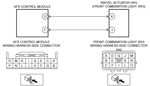
•  Open circuit in wiring harness between the following terminals:
―  AFS control module terminal D—Front combination light (RH) terminal K
―  AFS control module terminal F—Front combination light (RH) terminal J
•  Swivel actuator (RH) malfunction
•  AFS control module malfunction

Diagnostic Procedure

Step

Inspection

Action

1
VERIFY IGNITER (RH) INSTALLATION CONDITION
•  Verify the installation condition of the igniter (RH).
•  Is the igniter (RH) installed correctly?
Yes
Go to the next step.
No
Install the igniter (RH) correctly, then go to Step 6.
2
INSPECT FRONT COMBINATION LIGHT (RH) CONNECTOR CONDITION
•  Switch the ignition off.
•  Disconnect the front combination light (RH) connector.
•  Inspect the connector engagement and connection condition and inspect the terminals for damage, deformation, corrosion, or disconnection.
•  Is the connector normal?
Yes
Go to the next step.
No
Repair or replace the connector, then go to Step 6.
3
INSPECT AFS CONTROL MODULE CONNECTOR CONDITION
•  Disconnect the AFS control module connector.
•  Inspect the connector engagement and connection condition and inspect the terminals for damage, deformation, corrosion, or disconnection.
•  Is the connector normal?
Yes
Go to the next step.
No
Repair or replace the connector, then go to Step 6.
4
INSPECT FOR OPEN CIRCUIT IN SWIVEL ACTUATOR (RH) CIRCUIT
•  Verify that the front combination light (RH) and AFS control module connectors are disconnected.
•  Inspect for continuity between the following terminals (wiring harness-side):
―  AFS control module terminal D—Front combination light (RH) terminal K
―  AFS control module terminal F—Front combination light (RH) terminal J
•  Is there continuity?
Yes
Go to the next step.
No
Refer to the wiring diagram and verify whether or not there is a common connector between the following terminals:
•  AFS control module terminal D—Front combination light (RH) terminal K
•  AFS control module terminal F—Front combination light (RH) terminal J
If there is a common connector:
•  Determine the malfunctioning part by inspecting the common connector and the terminal for corrosion, damage, or pin disconnection, and the common wiring harness for an open circuit.
•  Repair or replace the malfunctioning part.
If there is no common connector:
•  Repair or replace the wiring harness which has an open circuit.
Go to Step 6.
5
PERFORM DTC INSPECTION AND VERIFY SWIVEL ACTUATOR (RH) MALFUNCTION
•  Always reconnect all disconnected connectors.
•  Clear the DTC for the AFS control module using the M-MDS.
•  Switch the ignition ON (engine off or on) and wait for 5 s or more.
•  Retrieve the AFS control module DTCs using the M-MDS.
•  Is the same DTC displayed?
Yes
Replace the front combination light (RH), then go to the next step.
No
Go to Step 7.
6
VERIFY THAT REPAIRS HAVE BEEN COMPLETED
•  Always reconnect all disconnected connectors.
•  Clear the DTC for the AFS control module using the M-MDS.
•  Switch the ignition ON (engine off or on) and wait for 5 s or more.
•  Retrieve the AFS control module DTCs using the M-MDS.
•  Is the same DTC displayed?
Yes
Repeat the inspection from Step 1.
•  If the malfunction recurs, replace the AFS control module.
Go to the next step.
No
Go to the next step.
7
VERIFY IF OTHER DTCs DISPLAYED
•  Are any other DTCs displayed?
Yes
Repair or replace the malfunctioning part according to the applicable DTC troubleshooting.
No
DTC troubleshooting completed.