|
1
|
VERIFY DTCs WITH REMOTE TRANSMITTER IN DIFFERENT LOCATIONS
• Clear the DTC for the immobilizer system using the M-MDS.
• Perform the following procedure 3 times with the remote transmitter inside the cabin with certainty.
-
1. Switch the ignition off.
2. Switch the ignition ON (engine off or on).
3. Retrieve the immobilizer system DTCs using the M-MDS.
4. Move the remote transmitter to a different location.
• Is the security indicator light: 13, DTC B13D3:94/P1260:00 displayed?
|
Yes
|
Go to the next step.
|
|
No
|
Go to Step 10.
|
|
2
|
PERFORM DTC INSPECTION AND VERIFY KEYLESS RECEIVER MALFUNCTION
• Clear the DTC for the start stop unit using the M-MDS.
• Retrieve the start stop unit DTCs using the M-MDS.
• Is DTC U201F:11/U201F:12 displayed?
|
Yes
|
Repair or replace the malfunctioning part according to the applicable DTC troubleshooting.
|
|
No
|
Go to the next step.
|
|
3
|
INSPECT PUSH BUTTON START CONNECTOR CONDITION
• Switch the ignition off.
• Disconnect the negative battery cable.
• Disconnect the push button start connector.
• Inspect the connector engagement and connection condition and inspect the terminals for damage, deformation, corrosion, or disconnection.
• Is the connector normal?
|
Yes
|
Go to the next step.
|
|
No
|
Repair or replace the connector, then go to Step 9.
|
|
4
|
INSPECT KEYLESS RECEIVER CONNECTOR CONDITION
• Disconnect the keyless receiver connector.
• Inspect the connector engagement and connection condition and inspect the terminals for damage, deformation, corrosion, or disconnection.
• Is the connector normal?
|
Yes
|
Go to the next step.
|
|
No
|
Repair or replace the connector, then go to Step 9.
|
|
5
|
INSPECT START STOP UNIT CONNECTOR CONDITION
• Disconnect the start stop unit connector.
• Inspect the connector engagement and connection condition and inspect the terminals for damage, deformation, corrosion, or disconnection.
• Is the connector normal?
|
Yes
|
Go to the next step.
|
|
No
|
Repair or replace the connector, then go to Step 9.
|
|
6
|
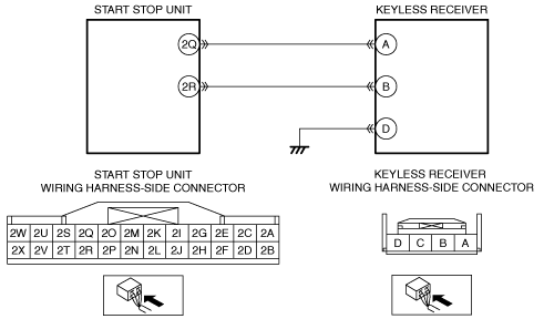
INSPECT FOR OPEN CIRCUIT IN KEYLESS RECEIVER CIRCUIT
• Verify that the start stop unit and keyless receiver connectors are disconnected.
• Inspect for continuity between the following terminals (wiring harness-side):
-
― Start stop unit terminal 2Q—Keyless receiver terminal A
― Start stop unit terminal 2R—Keyless receiver terminal B
• Is there continuity?
|
Yes
|
Go to the next step.
|
|
No
|
Refer to the wiring diagram and verify whether or not there is a common connector between the following terminals:
• Start stop unit terminal 2Q—Keyless receiver terminal A
• Start stop unit terminal 2R—Keyless receiver terminal B
If there is a common connector:
• Determine the malfunctioning part by inspecting the common connector and the terminal for corrosion, damage, or pin disconnection, and the common wiring harness for an open circuit.
• Repair or replace the malfunctioning part.
If there is no common connector:
• Repair or replace the wiring harness which has an open circuit.
Go to Step 9.
|
|
7
|
INSPECT REMOTE TRANSMITTER BATTERY POWER
• Always reconnect all disconnected connectors.
• Connect the negative battery cable.
• Inspect the battery power of the remote transmitter.
• Does the KEY indicator light (green) flash for approx. 30 s?
|
Yes
|
-
Note
-
• If the KEY indicator light (green) flashes for approx. 30 s, the battery power of the remote transmitter is low.
Replace the remote transmitter battery and go to Step 9.
|
|
No
|
Go to the next step.
|
|
8
|
VERIFY IF MALFUNCTION CAUSE IS REMOTE TRANSMITTER
• Always reconnect all disconnected connectors.
• Reconnect the negative battery cable.
• Clear the DTC for the immobilizer system using the M-MDS.
• Re-program key ID number of the remote transmitter.
• Retrieve the immobilizer system DTCs using the M-MDS.
• Is the security indicator light: 13, DTC B13D3:94/P1260:00 displayed?
|
Yes
|
Replace the remote transmitter, then go to the next step.
|
|
No
|
Go to Step 10.
|
|
9
|
VERIFY THAT REPAIRS HAVE BEEN COMPLETED
• Always reconnect all disconnected connectors.
• Reconnect the disconnected negative battery cable.
• Clear the DTC for the immobilizer system using the M-MDS.
• Retrieve the immobilizer system DTCs using the M-MDS.
• Is the security indicator light: 13, DTC B13D3:94/P1260:00 displayed?
|
Yes
|
Repeat the inspection from Step 1.
• If the malfunction recurs, replace the start stop unit.
Go to the next step.
|
|
No
|
Go to the next step.
|
|
10
|
VERIFY IF OTHER DTCs DISPLAYED
• Are any other DTCs displayed?
|
Yes
|
Repair or replace the malfunctioning part according to the applicable DTC troubleshooting.
|
|
No
|
DTC troubleshooting completed.
|