|
1
|
INSPECT PUSH BUTTON START CONNECTOR CONDITION
• Switch the ignition off.
• Disconnect the negative battery cable.
• Disconnect the push button start connector.
• Inspect the connector engagement and connection condition and inspect the terminals for damage, deformation, corrosion, or disconnection.
• Is the connector normal?
|
Yes
|
Go to the next step.
|
|
No
|
Repair or replace the connector, then go to Step 6.
|
|
2
|
INSPECT START STOP UNIT CONNECTOR CONDITION
• Disconnect the start stop unit connector.
• Inspect the connector engagement and connection condition and inspect the terminals for damage, deformation, corrosion, or disconnection.
• Is the connector normal?
|
Yes
|
Go to the next step.
|
|
No
|
Repair or replace the connector, then go to Step 6.
|
|
3
|
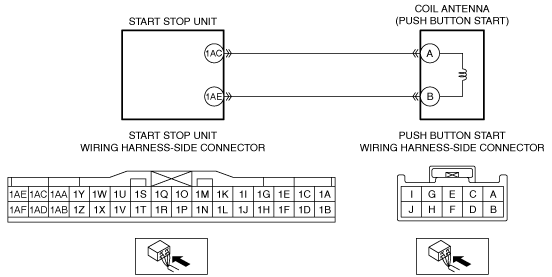
INSPECT FOR SHORT TO GROUND IN COIL ANTENNA CIRCUIT
• Verify that the push button start and start stop unit connectors are disconnected.
• Inspect for continuity between the following terminals (wiring harness-side) and body ground:
-
― Push button start terminal A
― Push button start terminal B
• Is there continuity?
|
Yes
|
Refer to the wiring diagram and verify whether or not there is a common connector between the following terminals:
• Start stop unit terminal 1AC—Push button start terminal A
• Start stop unit terminal 1AE—Push button start terminal B
If there is a common connector:
• Determine the malfunctioning part by inspecting the common connector and the terminal for corrosion, damage, or pin disconnection, and the common wiring harness for a short to ground.
• Repair or replace the malfunctioning part.
If there is no common connector:
• Repair or replace the wiring harness which has a short to ground.
Go to Step 6.
|
|
No
|
Go to the next step.
|
|
4
|
INSPECT FOR OPEN CIRCUIT IN COIL ANTENNA CIRCUIT
• Verify that the push button start and start stop unit connectors are disconnected.
• Inspect for continuity between the following terminals (wiring harness-side):
-
― Start stop unit terminal 1AC—Push button start terminal A
― Start stop unit terminal 1AE—Push button start terminal B
• Is there continuity?
|
Yes
|
Go to the next step.
|
|
No
|
Refer to the wiring diagram and verify whether or not there is a common connector between the following terminals:
• Start stop unit terminal 1AC—Push button start terminal A
• Start stop unit terminal 1AE—Push button start terminal B
If there is a common connector:
• Determine the malfunctioning part by inspecting the common connector and the terminal for corrosion, damage, or pin disconnection, and the common wiring harness for an open circuit.
• Repair or replace the malfunctioning part.
If there is no common connector:
• Repair or replace the wiring harness which has an open circuit.
Go to Step 6.
|
|
5
|
PERFORM DTC INSPECTION AND VERIFY COIL ANTENNA MALFUNCTION
• Always reconnect all disconnected connectors.
• Remove the ROOM 15 A fuse.
• Reconnect the negative battery cable.
• Clear the DTC for the immobilizer system using the M-MDS.
• Retrieve the immobilizer system DTCs using the M-MDS.
• Is the security indicator light: 11, DTC B10D9:87/P1260:00 displayed?
|
Yes
|
Replace the push button start, then go to the next step.
|
|
No
|
Go to Step 7.
|
|
6
|
VERIFY THAT REPAIRS HAVE BEEN COMPLETED
• Always reconnect all disconnected connectors.
• Remove the ROOM 15 A fuse.
• Reconnect the negative battery cable.
• Clear the DTC for the immobilizer system using the M-MDS.
• Retrieve the immobilizer system DTCs using the M-MDS.
• Is the security indicator light: 11, DTC B10D9:87/P1260:00 displayed?
|
Yes
|
Repeat the inspection from Step 1.
• If the malfunction recurs, replace the start stop unit.
Go to the next step.
|
|
No
|
Go to the next step.
|
|
7
|
VERIFY IF OTHER DTCs DISPLAYED
• Are any other DTCs displayed?
|
Yes
|
Repair or replace the malfunctioning part according to the applicable DTC troubleshooting.
|
|
No
|
DTC troubleshooting completed.
|