DTC B10E7:12 [START STOP UNIT]


id0902p6020100

Description

IG1 relay circuit malfunction

Detection condition
•  Start stop unit detects the IG1 relay output monitor voltage of 2.5 V or more for 0.5 s or more with the ignition switched off or ACC.
Fail-safe function
•  Door locking operation inhibited while under i-stop control. (With i-stop system)
Possible cause
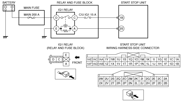
•  IG1 relay malfunction
•  Start stop unit connector or terminal malfunction
•  Short to power supply in wiring harness between IG1 relay terminal A and start stop unit terminal 2S
•  Start stop unit malfunction

Diagnostic Procedure

Step

Inspection

Action

1
INSPECT IG1 RELAY
•  Switch the ignition off.
•  Remove the IG1 relay.
•  Inspect the IG1 relay.
•  Is the IG1 relay normal?
Yes
Go to the next step.
No
Replace the IG1 relay, then go to Step 4.
2
INSPECT START STOP UNIT CONNECTOR CONDITION
•  Disconnect the start stop unit connector.
•  Inspect the connector engagement and connection condition and inspect the terminals for damage, deformation, corrosion, or disconnection.
•  Is the connector normal?
Yes
Go to the next step.
No
Repair or replace the connector, then go to Step 4.
3
INSPECT FOR SHORT TO POWER SUPPLY IN IG1 RELAY CIRCUIT
•  Always reconnect all disconnected connectors.
•  Measure the voltage at the start stop unit terminal 2S (wiring harness-side).
•  Is the voltage 2.5 V or more?
Yes
Refer to the wiring diagram and verify whether or not there is a common connector between IG1 relay terminal A and start stop unit terminal 2S.
If there is a common connector:
•  Determine the malfunctioning part by inspecting the common connector and the terminal for corrosion, damage, or pin disconnection, and the common wiring harness for a short to power supply.
•  Repair or replace the malfunctioning part.
If there is no common connector:
•  Repair or replace the wiring harness which has a short to power supply.
Go to the next step.
No
Go to the next step.
4
VERIFY THAT REPAIRS HAVE BEEN COMPLETED
•  Always reconnect all disconnected connectors.
•  Clear the DTC for the start stop unit using the M-MDS.
•  Switch the ignition off and wait for 1 s or more.
•  Retrieve the start stop unit DTCs using the M-MDS.
•  Is the same DTC displayed?
Yes
Repeat the inspection from Step 1.
•  If the malfunction recurs, replace the start stop unit.
Go to the next step.
No
Go to the next step.
5
VERIFY IF OTHER DTCs DISPLAYED
•  Are any other DTCs displayed?
Yes
Repair or replace the malfunctioning part according to the applicable DTC troubleshooting.
No
DTC troubleshooting completed.