 |
am3uuw00010426
HAZARD WARNING SWITCH INSPECTION
id091800803100
Continuity Inspection
1. Disconnect the negative battery cable. (See NEGATIVE BATTERY CABLE DISCONNECTION/CONNECTION [MZR 1.6].) (See NEGATIVE BATTERY CABLE DISCONNECTION/CONNECTION [SKYACTIV-G 1.5, SKYACTIV-G 2.0, SKYACTIV-G 2.5].) (See NEGATIVE BATTERY CABLE DISCONNECTION/CONNECTION [SKYACTIV-D 2.2].)(See NEGATIVE BATTERY CABLE DISCONNECTION/CONNECTION [SKYACTIV-D 1.5].)
2. Remove the glove compartment. (See GLOVE COMPARTMENT REMOVAL/INSTALLATION.)
3. Remove the decoration panel. (See DECORATION PANEL REMOVAL/INSTALLATION.)
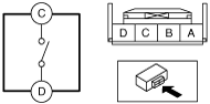
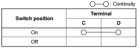
4. Verify that the continuity between the hazard warning switch terminals is as indicated in the table.
am3uuw00010426
|
am6zzw00008069
|
LED Illumination Inspection
1. Disconnect the negative battery cable. (See NEGATIVE BATTERY CABLE DISCONNECTION/CONNECTION [MZR 1.6].) (See NEGATIVE BATTERY CABLE DISCONNECTION/CONNECTION [SKYACTIV-G 1.5, SKYACTIV-G 2.0, SKYACTIV-G 2.5].) (See NEGATIVE BATTERY CABLE DISCONNECTION/CONNECTION [SKYACTIV-D 2.2].) (See NEGATIVE BATTERY CABLE DISCONNECTION/CONNECTION [SKYACTIV-D 1.5].)
2. Remove the glove compartment. (See GLOVE COMPARTMENT REMOVAL/INSTALLATION.)
3. Remove the decoration panel. (See DECORATION PANEL REMOVAL/INSTALLATION.)
4. Apply battery voltage to hazard warning switch terminal A, and connect terminal B to ground.
am3uuw00010427
|
5. Verify that the LED is turned on.