-
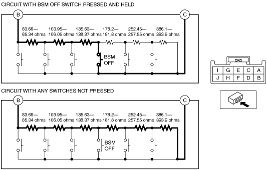
• Resistance with BSM OFF switch pressed and held
-
― 323.24—329.76 ohms
-
-
• Resistance with any switches not pressed
-
― 1,139.99—1,163.01 ohms
-
am3zzw00015329
|
BLIND SPOT MONITORING (BSM) OFF SWITCH INSPECTION
id092200014200
Resistance Inspection
1. Disconnect the negative battery cable. (See NEGATIVE BATTERY CABLE DISCONNECTION/CONNECTION [SKYACTIV-G 1.5, SKYACTIV-G 2.0, SKYACTIV-G 2.5].) (See NEGATIVE BATTERY CABLE DISCONNECTION/CONNECTION [SKYACTIV-D 2.2].)
2. Remove the following parts:
3. Measure the resistance between cluster switch terminals B and C under the following conditions:
am3zzw00015329
|
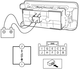
LED Illumination Inspection
1. Disconnect the negative battery cable. (See NEGATIVE BATTERY CABLE DISCONNECTION/CONNECTION [SKYACTIV-G 1.5, SKYACTIV-G 2.0, SKYACTIV-G 2.5].) (See NEGATIVE BATTERY CABLE DISCONNECTION/CONNECTION [SKYACTIV-D 2.2].)
2. Remove the following parts:
3. Apply battery positive voltage to cluster switch terminal J, and connect terminal I to ground.
ac5jjw00000654
|
4. Verify that the LED illuminates.