am6zzw00011822
|
DTC P0300:00 [SKYACTIV-G 1.5, SKYACTIV-G 2.0, SKYACTIV-G 2.5]
id0102h9703200
Details On DTCs
|
DESCRIPTION |
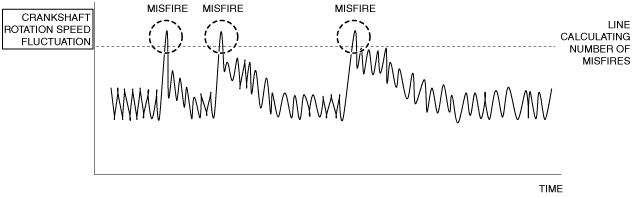
Random misfire detected |
|
|---|---|---|
|
DETECTION CONDITION
|
Determination conditions
|
• Any one of the following conditions is met:
|
|
Preconditions
|
• Battery voltage: 9—18 V*1
• Engine speed: 500—4,500 rpm*1
• Engine coolant temperature: 20 °C {68 °F} or more*1
• Fuel-cut control not implemented
• Crankshaft installation tolerance learning completed
• Engine condition is stabilized (not directly after gear change)
*1: Value can be verified by displaying PIDs using the M-MDS.
|
|
|
Malfunction determination period
|
• 200 rotations of crankshaft (misfire which may damage catalytic converter)
• 1,000 rotations of crankshaft (misfire going against emission regulations)
|
|
|
Drive cycle
|
• 2
|
|
|
Self test type
|
• CMDTC self test
|
|
|
Sensor used
|
• CKP sensor
• MAF sensor
• MAP sensor
|
|
|
FAIL-SAFE FUNCTION
|
• Limits intake air amount
• Implement fuel-cut control (if the catalytic converter may be damaged, perform fuel-cut on cylinder misfiring the most).
|
|
|
VEHICLE STATUS WHEN DTCs ARE OUTPUT
|
• Misfiring which may damage catalytic converter (number of drive cycles: 1):
• Drive cycle directly after above drive cycle (number of drive cycles: 2):
• Rough idling, poor acceleration, stalling
|
|
|
POSSIBLE CAUSE
|
• Improper operation of ignition system
• Fuel injector malfunction
• Erratic signal to PCM
• Poor drive belt assembly or adhesion of oil
• Drive belt auto tensioner malfunction
• Air leakage from intake air system (between intake manifold and cylinder head)
• Engine malfunction
• PCM malfunction
|
|
System Wiring Diagram
Function Explanation (DTC Detection Outline)
am6zzw00011822
|
Repeatability Verification Procedure
PID Item/Simulation Item Used In Diagnosis
PID/DATA monitor item table
|
Item |
Definition |
Unit |
Condition/Specification |
|---|---|---|---|
|
APP1
|
Accelerator pedal opening angle (absolute value) input from APP sensor No.1
|
%
|
• Accelerator pedal released: Approx. 15%
• Accelerator pedal fully depressed: Approx. 82%
|
|
APP sensor No.1 voltage
|
V
|
• Accelerator pedal released: Approx. 0.75 V
• Accelerator pedal fully depressed: Approx. 4.1 V
|
|
|
APP2
|
Accelerator pedal opening angle (absolute value) input from APP sensor No.2
|
%
|
• Accelerator pedal released: Approx. 7.45%
• Accelerator pedal fully depressed: Approx. 41%
|
|
APP sensor No.2 voltage
|
V
|
• Accelerator pedal released: Approx. 0.38 V
• Accelerator pedal fully depressed: Approx. 2.05 V
|
|
|
ECT
|
Engine coolant temperature
|
°C, °F
|
• Displays ECT
|
|
ECT sensor voltage
|
V
|
• ECT is 20 °C {68 °F}: Approx. 3.10 V
• ECT is 40 °C {104 °F}: Approx. 2.16 V
• ECT is 60 °C {140 °F}: Approx. 1.40 V
• ECT is 80 °C {176 °F}: Approx. 0.87 V
• ECT is 100 °C {212 °F}: Approx. 0.54 V
|
|
|
IAT
|
Intake air temperature (No.1)
|
°C, °F
|
• Displays IAT (No.1)
|
|
IAT sensor No.1 voltage
|
V
|
• IAT is 20 °C {68 °F}: Approx. 2.70 V
• IAT is 40 °C {104 °F}: Approx. 1.80 V
• IAT is 60 °C {140 °F}: Approx. 1.20 V
|
|
|
MAF
|
Mass air flow
|
g/Sec
|
• Displays MAF
|
|
MAF sensor voltage
|
V
|
• Ignition switched ON (engine off) (MAF: 0.59 g/s {0.078 lb/min}): Approx. 0.72 V
• Idle (after warm up) (MAF: 2.17 g/s {0.287 lb/min}): Approx. 0.86 V
• Racing (engine speed is 2,000 rpm) (MAF: 4.73 g/s {0.626 lb/min}): Approx. 1.07 V
|
|
|
MAP
|
Manifold absolute pressure
|
KPa {MPa}, mBar {Bar}, psi, in H20
|
• Displays MAP
|
|
MAP sensor voltage
|
V
|
• Ignition switched ON (engine off) (MAP:101 kPa {1.03 kgf/cm2, 14.6 psi}): Approx. 4.07 V
• Idle (after warm up) (MAP: 33 kPa {0.34 kgf/cm2, 4.8 psi}): Approx. 1.34 V
• Racing (engine speed is 2,000 rpm) (MAP: 26 kPa {0.27 kgf/cm2, 3.8 psi}): Approx. 1.05 V
|
|
|
MF_CAT1
|
Number of misfires in No.1 cylinder leading to catalytic converter temperature increase (catalytic converter temperature increases due to fuel combustion around catalytic converter after misfire)
|
—
|
• Displays number of misfires corresponding to possible catalytic converter damage (No.1 cylinder)
|
|
MF_CAT_2
|
Number of misfires in No.2 cylinder leading to catalytic converter temperature increase (catalytic converter temperature increases due to fuel combustion around catalytic converter after misfire)
|
—
|
• Displays number of misfires corresponding to possible catalytic converter damage (No.2 cylinder)
|
|
MF_CAT_3
|
Number of misfires in No.3 cylinder leading to catalytic converter temperature increase (catalytic converter temperature increases due to fuel combustion around catalytic converter after misfire)
|
—
|
• Displays number of misfires corresponding to possible catalytic converter damage (No.3 cylinder)
|
|
MF_CAT_4
|
Number of misfires in No.4 cylinder leading to catalytic converter temperature increase (catalytic converter temperature increases due to fuel combustion around catalytic converter after misfire)
|
—
|
• Displays number of misfires corresponding to possible catalytic converter damage (No.4 cylinder)
|
|
MF_EMI1
|
Number of misfires in No.1 cylinder under conditions required by emission regulations
|
—
|
• Displays number of misfires possibly affecting emission (No.1 cylinder)
|
|
MF_EMI_2
|
Number of misfires in No.2 cylinder under conditions required by emission regulations
|
—
|
• Displays number of misfires possibly affecting emission (No.2 cylinder)
|
|
MF_EMI_3
|
Number of misfires in No.3 cylinder under conditions required by emission regulations
|
—
|
• Displays number of misfires possibly affecting emission (No.3 cylinder)
|
|
MF_EMI_4
|
Number of misfires in No.4 cylinder under conditions required by emission regulations
|
—
|
• Displays number of misfires possibly affecting emission (No.4 cylinder)
|
|
RPM
|
Engine speed
|
RPM
|
• Displays engine speed
|
|
TP_REL
|
Throttle valve opening angle (relative value) with value at throttle valve fully open timing as the start point
|
%
|
• Accelerator pedal released: Approx. 12%
• Accelerator pedal fully depressed: Approx. 82%
|
|
VSS
|
Vehicle speed
|
KPH, MPH
|
• Displays vehicle speed
|
Function Inspection Using M-MDS
|
STEP |
INSPECTION |
RESULTS |
ACTION |
|---|---|---|---|
|
1
|
PURPOSE: VERIFY RELATED SERVICE INFORMATION AVAILABILITY
• Verify related Service Information availability.
• Is any related Service Information available?
|
Yes
|
Perform repair or diagnosis according to the available Service Information.
• If the vehicle is not repaired, go to the next step.
|
|
No
|
Go to the next step.
|
||
|
2
|
PURPOSE: IDENTIFY TRIGGER DTC FOR FREEZE FRAME DATA (MODE 2)
• Is the DTC P0300:00 on FREEZE FRAME DATA (Mode 2)?
|
Yes
|
Go to the next step.
|
|
No
|
Go to the troubleshooting procedure for DTC on FREEZE FRAME DATA (Mode 2).
|
||
|
3
|
PURPOSE: RECORD VEHICLE STATUS AT TIME OF DTC DETECTION TO UTILIZE WITH REPEATABILITY VERIFICATION
• Has the FREEZE FRAME DATA (Mode 2)/snapshot data been recorded?
|
Yes
|
Go to the next step.
|
|
No
|
Record the FREEZE FRAME DATA (Mode 2)/snapshot data on the repair order, then go to the next step.
|
||
|
4
|
PURPOSE: VERIFY RELATED PENDING CODE AND/OR DTC
• Switch the ignition off, then ON (engine off).
• Perform the Pending Trouble Code Access Procedure and DTC Reading Procedure.
• Are any other PENDING CODEs and/or DTCs present?
|
Yes
|
Go to the applicable PENDING CODE or DTC inspection.
|
|
No
|
Go to the next step.
|
||
|
5
|
PURPOSE: VERIFY IF THERE IS PID ITEM CAUSING DRASTIC CHANGES OF ACCELERATION FLUCTUATION BY INPUT SIGNAL TO PCM
• Start the engine.
• Access the following PIDs using the M-MDS:
• Is there a PID item affected by acceleration fluctuation?
|
Yes
|
Inspect the suspected sensor and related wiring harness.
• If there is any malfunction:
• If there is no malfunction:
|
|
No
|
Go to the next step.
|
||
|
6
|
PURPOSE: RECORD NUMBER OF CURRENT MISFIRES DURING NO LOAD TO SPECIFY MISFIRING CYLINDER
• Start the engine.
• Verify all accessory loads (A/C, headlights, blower fan, rear window defroster) are off.
• Under no-load conditions (P or N position (ATX)/neutral (MTX)), increase the engine speed to 3,000 rpm and hold for 30 s.
• Verify the number of misfires.
• Can a misfire be verified?
|
Yes
|
Record each of the verified values, then go to the next step.
|
|
No
|
Go to step 9.
|
||
|
7
|
PURPOSE: VERIFY IF MISFIRE CAUSE IS BAD SPARK PLUGS
• Switch the spark plugs on a cylinder that is misfiring and a cylinder that is not misfiring.
• Start the engine.
• Verify all accessory loads (A/C, headlights, blower fan, rear window defroster) are off.
• Under no-load conditions (P or N position (ATX)/neutral (MTX)), increase the engine speed to 3,000 rpm and hold for 30 s.
• Verify the number of misfires.
• Is there a change from the recorded number of misfires in Step 6?
|
Yes
|
Go to the troubleshooting procedure to perform the procedure from Step 1.
|
|
No
|
Go to the next step.
|
||
|
8
|
PURPOSE: VERIFY IF MISFIRE CAUSE IS BAD IGNITION COIL
• Switch the ignition coils on a cylinder that is misfiring and a cylinder that is not misfiring.
• Start the engine.
• Verify all accessory loads (A/C, headlights, blower fan, rear window defroster) are off.
• Under no-load conditions (P or N position (ATX)/neutral (MTX)), increase the engine speed to 3,000 rpm and hold for 30 s.
• Verify the number of misfires.
• Is there a change from the recorded number of misfires in Step 6?
|
Yes
|
Go to the troubleshooting procedure to perform the procedure from Step 2.
|
|
No
|
Go to the troubleshooting procedure to perform the procedure from Step 3.
|
||
|
9
|
PURPOSE: RECORD NUMBER OF CURRENT MISFIRES WHILE DRIVING UNDER LOAD TO SPECIFY MISFIRING CYLINDER
• Start the engine.
• Verify the number of misfires while the vehicle is being driven for 1 min under the condition of the freeze frame data (mode 2) recorded in Step 3.
• Can a misfire be verified?
|
Yes
|
Record each of the verified values, then go to the next step.
|
|
No
|
Referring to the service questioning results, verify the misfire rate again with the driving mode data added before recording the freeze frame data (mode 2)/snap shot data.
|
||
|
10
|
PURPOSE: VERIFY IF MISFIRE CAUSE IS BAD SPARK PLUGS
• Switch the spark plugs on a cylinder that is misfiring and a cylinder that is not misfiring.
• Start the engine.
• Verify the number of misfires while the vehicle is being driven for 1 min under the condition of the freeze frame data (mode 2) recorded in Step 9.
• Is there a change from the recorded number of misfires in Step 9?
|
Yes
|
Go to the troubleshooting procedure to perform the procedure from Step 1.
|
|
No
|
Go to the next step.
|
||
|
11
|
PURPOSE: VERIFY IF MISFIRE CAUSE IS BAD IGNITION COIL
• Switch the ignition coils on a cylinder that is misfiring and a cylinder that is not misfiring.
• Start the engine.
• Verify the number of misfires while the vehicle is being driven for 1 min under the condition of the freeze frame data (mode 2) recorded in Step 9.
• Is there a change from the recorded number of misfires in Step 9?
|
Yes
|
Go to the troubleshooting procedure to perform the procedure from Step 2.
|
|
No
|
Go to the troubleshooting procedure to perform the procedure from Step 3.
|
Troubleshooting Diagnostic Procedure
|
STEP |
INSPECTION |
RESULTS |
ACTION |
|---|---|---|---|
|
1
|
PURPOSE: DETERMINE INTEGRITY OF SPARK PLUG
• Inspect the spark plug.
• Is there any malfunction?
|
Yes
|
Replace the spark plug, then go to Step 10.
|
|
No
|
Go to the next step.
|
||
|
2
|
PURPOSE: DETERMINE INTEGRITY OF IGNITION COIL
• Inspect the ignition coil.
• Is there any malfunction?
|
Yes
|
Replace the ignition coil/ion sensor, then go to Step 10.
|
|
No
|
Go to the next step.
|
||
|
3
|
PURPOSE: DETERMINE INTEGRITY OF FUEL INJECTOR
• Inspect the fuel injector.
• Is there any malfunction?
|
Yes
|
Replace the fuel injector, then go to Step 10.
|
|
No
|
Go to the next step.
|
||
|
4
|
PURPOSE: VERIFY IF MALFUNCTION RELATED TO INTAKE-AIR SYSTEM IS CAUSE OF MISFIRE
• Visually inspect for loose, cracked or damaged hoses on intake air system.
• Is there any malfunction?
|
Yes
|
Repair or replace the malfunctioning part according to the inspection results, then go to Step 10.
|
|
No
|
Go to the next step.
|
||
|
5
|
PURPOSE: VERIFY IF POOR DRIVE BELT ASSEMBLY IS CAUSE OF MISFIRE
• Verify the condition of the drive belt assembly.
• Is there any malfunction?
|
Yes
|
Assemble drive belt correctly, then go to Step 10.
|
|
No
|
Go to the next step.
|
||
|
6
|
PURPOSE: VERIFY IF FOREIGN MATTER ON DRIVE BELT IS CAUSE OF MISFIRE
• Verify if oil is on the drive belt.
• Is there foreign matter on the drive belt?
|
Yes
|
Remove the foreign matter on the drive belt, then go to Step 10.
|
|
No
|
Go to the next step.
|
||
|
7
|
PURPOSE: DETERMINE INTEGRITY OF DRIVE BELT AUTO TENSIONER
• Inspect the drive belt auto tensioner.
• Is there any malfunction?
|
Yes
|
Replace the drive belt auto tensioner, then go to Step 10.
|
|
No
|
Go to the next step.
|
||
|
8
|
PURPOSE: VERIFY IF MALFUNCTION RELATED TO ENGINE COMPRESSION IS CAUSE OF MISFIRE
• Inspect the engine compression.
• Are compression pressures within specification?
Specification:
• Compression [SKYACTIV-G 1.5]
• Compression [SKYACTIV-G 2.0, European (L.H.D. U.K.) specs.]
• Compression [SKYACTIV-G 2.0, Except European (L.H.D. U.K.) specs.]
• Compression [SKYACTIV-G 2.5]
|
Yes
|
Go to the next step.
|
|
No
|
Replace or overhaul the engine, then go to Step 10.
|
||
|
9
|
PURPOSE: VERIFY IF MALFUNCTION RELATED TO SEALING OF ENGINE UNIT (COMBUSTION CHAMBER AND ENGINE COOLANT PASSAGE) IS CAUSE OF MISFIRE
• Perform the “ENGINE COOLANT LEAKAGE INSPECTION”.
• Does the radiator cap tester needle drop even though there is no engine coolant leakage from the radiator or the hoses?
|
Yes
|
Engine coolant leakage from the engine (between the combustion chamber and the engine coolant passage) may have occurred.
• Verify the conditions of the gasket and the cylinder head.
|
|
No
|
Go to the next step.
|
||
|
10
|
PURPOSE: VERIFICATION OF VEHICLE REPAIR COMPLETION
• Always reconnect all disconnected connectors.
• Clear the DTC from the PCM memory using the M-MDS.
• Implement the repeatability verification procedure.
• Perform the Pending Trouble Code Access Procedure.
• Is the PENDING CODE for this DTC present?
|
Yes
|
Repeat the inspection from Step 1.
• If the malfunction recurs, replace the PCM.
Go to the next step.
|
|
No
|
Go to the next step.
|
||
|
11
|
PURPOSE: VERIFY IF THERE IS ANY OTHER MALFUNCTION
• Is any other DTC or pending code stored?
|
Yes
|
Go to the applicable DTC inspection.
|
|
No
|
DTC troubleshooting completed.
|