 |
FUEL INJECTOR REMOVAL/INSTALLATION [SKYACTIV-G 1.5, SKYACTIV-G 2.0, SKYACTIV-G 2.5]
id0114zc800600
1. Complete the “BEFORE SERVICE PRECAUTION”. (See BEFORE SERVICE PRECAUTION [SKYACTIV-G 1.5, SKYACTIV-G 2.0, SKYACTIV-G 2.5].)
2. Disconnect the negative battery cable. (See NEGATIVE BATTERY CABLE DISCONNECTION/CONNECTION [SKYACTIV-G 1.5, SKYACTIV-G 2.0, SKYACTIV-G 2.5].)
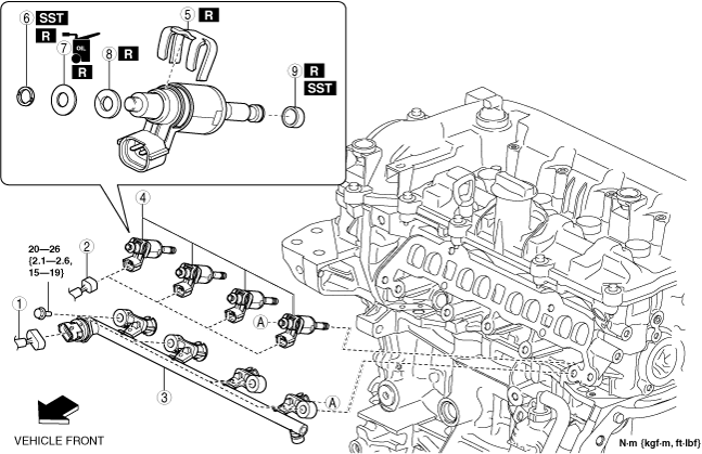
3. Remove the plug hole plate. (See PLUG HOLE PLATE REMOVAL/INSTALLATION [SKYACTIV-G 1.5, SKYACTIV-G 2.0, SKYACTIV-G 2.5].)
4. Remove the intake manifold. (See INTAKE-AIR SYSTEM REMOVAL/INSTALLATION [SKYACTIV-G 1.5, SKYACTIV-G 2.0, SKYACTIV-G 2.5].)
5. Remove in the order indicated in the table.
6. Install in the reverse order of removal.
7. Complete the “AFTER SERVICE PRECAUTION”. (See AFTER SERVICE PRECAUTION [SKYACTIV-G 1.5, SKYACTIV-G 2.0, SKYACTIV-G 2.5].)
am2uuw00002342
|
|
1
|
Fuel pressure sensor connector
|
|
2
|
Fuel injector connector
|
|
3
|
Fuel distributor
|
|
4
|
Fuel injector
|
|
5
|
Spacer
(See Spacer Installation Note.)
|
|
6
|
Stopper ring
(See Stopper Ring Removal Note.)
|
|
7
|
O-ring
|
|
8
|
Back-up ring
|
|
9
|
Teflon seal
(See Teflon Seal Removal Note.)
|
Fuel Distributor Removal Note
1. Remove the high pressure fuel pipe. (See HIGH PRESSURE FUEL PUMP REMOVAL/INSTALLATION [SKYACTIV-G 1.5, SKYACTIV-G 2.0, SKYACTIV-G 2.5].)
2. Remove the fuel distributor.
Stopper Ring Removal Note
1. Remove the stopper ring as shown in the figure.
am3zzw00015552
|
Teflon Seal Removal Note
1. Stretch the teflon seal as shown in the figure.
am3zzw00015553
|
2. Remove the teflon seal as shown in the figure.
am3zzw00015554
|
Teflon Seal Installation Note
1. Apply engine oil to the SST.
am3zzw00015555
|
2. Install the SST with the mark on the SST facing the fuel injector.
am3zzw00015556
|
3. Insert a new teflon seal onto the SST.
am3zzw00015557
|
4. Install the SST equipped with the teflon seal to the end of the fuel injector.
am3zzw00015558
|
5. Using the SST, press on the teflon seal to the fuel injector side.
am3zzw00015559
|
6. Press on the teflon seal to the position indicated in the figure, then remove the SST.
am3zzw00015560
|
7. Install the teflon seal to the fuel injector by hand and remove the SST.
am3zzw00015561
|
8. Slide the SST to the end of the fuel injector.
am3zzw00015562
|
9. Hold the SST at the position shown in the figure and correctly position the teflon seal for more than 30 s.
am3zzw00015563
|
Back-up Ring Installation Note
1. Install the back-up ring being, making sure it is installed in the right direction.
am3zzw00015564
|
2. After installing the back-up ring, verify that it is installed correctly.
am3zzw00015565
|
Stopper Ring Installation Note
1. Set a new stopper ring on the SST as shown in the figure being careful of the stopper ring orientation, and press down the fuel injector until a click sound is heard.
am3zzw00015566
|
Spacer Installation Note
1. Install the spacer to the fuel injector while being careful of the spacer installation direction and position.
am2uuw00002343
|
Fuel Injector Installation Note
1. Apply engine oil to the fuel injector installation holes.
2. Insert the fuel injectors to the installation holes one by one, being careful of the direction the fuel injectors are pointed.
am3zzw00015567
|
Fuel Distributor Installation Note
1. Install the fuel distributor to the fuel injectors while aligning the projection of the spacer to the notch of the fuel distributor.
am3zzw00015568
|
2. Temporarily tighten the fuel distributor installation bolts until their heads contact the fuel distributors.
3. Turn the fuel distributor installation bolts a half a turn in the order shown in the figure.
am3zzw00015569
|
4. Turn the fuel distributor installation bolts another half a turn in the order shown in the figure (one turn including the half turn in Step 3).
5. Tighten the fuel distributor installation bolts in the order shown in the figure.