 |
am3zzw00017583
DTC P0A94:00 [SKYACTIV-D 1.5]
id0102q2004400
Details On DTCs
|
DESCRIPTION |
DC-DC converter: control circuit signal error |
|
|---|---|---|
|
DETECTION CONDITION
|
Determination conditions
|
• Internal malfunction signal from DC-DC converter via front body control module (FBCM) is received. (CAN/LIN communication).
• Input signal from the DC-DC converter limits the pressure increase time.
• Input signal from the DC-DC converter does not implement pressure increase after a pressure increase command to the DC-DC converter.
|
|
Preconditions
|
• Not applicable
|
|
|
Drive cycle
|
• 1
|
|
|
Self test type
|
• CMDTC self test
|
|
|
Sensor used
|
• Not applicable
|
|
|
FAIL-SAFE FUNCTION
|
• Not applicable
|
|
|
VEHICLE STATUS WHEN DTCs ARE OUTPUT
|
• Flashes i-stop warning light (amber).
|
|
|
POSSIBLE CAUSE
|
• DC-DC converter connector or terminals malfunction
• Short to ground or open circuit in DC-DC converter power supply circuit
• PCM connector or terminals malfunction
• Short to ground in wiring harness between DC-DC converter terminal F and PCM terminal 2P
• Short to power supply in wiring harness between DC-DC converter terminal F and PCM terminal 2P
• Open circuit in wiring harness between DC-DC converter terminal F and PCM terminal 2P
• Battery malfunction
• DC-DC converter malfunction
• Front body control module (FBCM) malfunction
• PCM malfunction
|
|
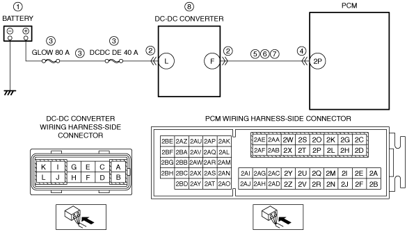
System Wiring Diagram
am3zzw00017583
|
Function Explanation (DTC Detection Outline)
Repeatability Verification Procedure
PID Item/Simulation Item Used In Diagnosis
Function Inspection Using M-MDS
|
STEP |
INSPECTION |
RESULTS |
ACTION |
|---|---|---|---|
|
1
|
PURPOSE: RECORD VEHICLE STATUS AT TIME OF DTC DETECTION TO UTILIZE WITH REPEATABILITY VERIFICATION
• Record the snapshot data on the repair order.
|
—
|
Go to the next step.
|
|
2
|
PURPOSE: VERIFY RELATED SERVICE INFORMATION AVAILABILITY
• Verify related Service Information availability.
• Is any related Service Information available?
|
Yes
|
Perform repair or diagnosis according to the available Service Information.
• If the vehicle is not repaired, go to the next step.
|
|
No
|
Go to the next step.
|
||
|
3
|
PURPOSE: VERIFY IF BATTERY VOLTAGE IS FALSELY RECOGNIZED BY DTC RELATED CAN OR LIN COMMUNICATION
• Switch the ignition off, then ON (engine off).
• Perform the PCM and front body control module (FBCM) DTC inspection using the M-MDS.
• Are DTCs related CAN or LIN communication recorded?
|
Yes
|
Repair or replace the malfunctioning part according to the applicable DTC troubleshooting.
(See DTC TABLE [SKYACTIV-D 1.5].)
Go to the next step.
|
|
No
|
Go to the next step.
|
||
|
4
|
PURPOSE: VERIFY IF THE CURRENT SENSOR IS MISIDENTIFYING MALFUNCTIONS DUE TO A FRONT BODY CONTROL MODULE (FBCM) MALFUNCTION
• Perform the front body control module (FBCM) DTC inspection using the M-MDS.
• Are any DTCs present?
|
Yes
|
Repair or replace the malfunctioning part according to the applicable DTC troubleshooting.
Go to the troubleshooting procedure to perform the procedure from Step 1.
|
|
No
|
Go to the troubleshooting procedure to perform the procedure from Step 1.
|
Troubleshooting Diagnostic Procedure
Diagnostic Procedure
|
STEP |
INSPECTION |
ACTION |
|
|---|---|---|---|
|
1
|
PURPOSE: INSPECT BATTERY
• Switch the ignition off.
• Inspect the battery.
• Is there any malfunction?
|
Yes
|
Recharge or replace the battery, then go to Step 8.
|
|
No
|
Go to the next step.
|
||
|
2
|
PURPOSE: INSPECT DC-DC CONVERTER CONNECTOR CONDITION
• Switch the ignition off.
• Disconnect the DC-DC converter connector.
• Inspect for poor connection (such as damaged/pulled-out pins, corrosion).
• Is there any malfunction?
|
Yes
|
Repair or replace the connector and/or terminals, then go to Step 8.
|
|
No
|
Go to the next step.
|
||
|
3
|
PURPOSE: INSPECT DC-DC CONVERTER POWER SUPPLY CIRCUIT FOR SHORT TO GROUND OR OPEN CIRCUIT
• Verify that the DC-DC converter connector is disconnected.
• Measure the voltage at the DC-DC converter terminal L (wiring harness-side).
• Is the voltage B+?
|
Yes
|
Go to the next step.
|
|
No
|
Inspect the GLOW 80 A fuse and DCDC DE 40 A fuse.
• If the fuse is blown:
• If the fuse is damaged:
• If all fuses are normal:
Go to Step 8.
|
||
|
4
|
PURPOSE: INSPECT PCM CONNECTOR CONDITION
• Disconnect the PCM connector.
• Inspect for poor connection (such as damaged/pulled-out pins, corrosion).
• Is there any malfunction?
|
Yes
|
Repair or replace the connector and/or terminals, then go to Step 8.
|
|
No
|
Go to the next step.
|
||
|
5
|
PURPOSE: INSPECT DC-DC CONVERTER SIGNAL CIRCUIT FOR SHORT TO GROUND
• Verify that the DC-DC converter and PCM connectors are disconnected.
• Inspect for continuity between DC-DC converter terminal F (wiring harness-side) and body ground.
• Is there continuity?
|
Yes
|
Refer to the wiring diagram and verify whether or not there is a common connector between DC-DC converter terminal F and PCM terminal 2P.
If there is a common connector:
• Determine the malfunctioning part by inspecting the common connector and the terminal for corrosion, damage, or pin disconnection, and the common wiring harness for a short to ground.
• Repair or replace the malfunctioning part.
If there is no common connector:
• Repair or replace the wiring harness which has a short to ground.
Go to Step 8.
|
|
No
|
Go to the next step.
|
||
|
6
|
PURPOSE: INSPECT DC-DC CONVERTER SIGNAL CIRCUIT FOR SHORT TO POWER SUPPLY
• Verify that the DC-DC converter and PCM connectors are disconnected.
• Switch the ignition ON (engine off).
• Measure the voltage at the DC-DC converter terminal F (wiring harness-side).
• Is the voltage 0 V?
|
Yes
|
Go to the next step.
|
|
No
|
Refer to the wiring diagram and verify whether or not there is a common connector between DC-DC converter terminal F and PCM terminal 2P.
If there is a common connector:
• Determine the malfunctioning part by inspecting the common connector and the terminal for corrosion, damage, or pin disconnection, and the common wiring harness for a short to power supply.
• Repair or replace the malfunctioning part.
If there is no common connector:
• Repair or replace the wiring harness which has a short to power supply.
Go to Step 8.
|
||
|
7
|
PURPOSE: INSPECT DC-DC CONVERTER SIGNAL CIRCUIT FOR OPEN CIRCUIT
• Verify that the DC-DC converter and PCM connectors are disconnected.
• Switch the ignition off.
• Inspect for continuity between DC-DC converter terminal F (wiring harness-side) and PCM terminal 2P (wiring harness-side).
• Is there continuity?
|
Yes
|
Go to the next step.
|
|
No
|
Refer to the wiring diagram and verify whether or not there is a common connector between DC-DC converter terminal F and PCM terminal 2P.
If there is a common connector:
• Determine the malfunctioning part by inspecting the common connector and the terminal for corrosion, damage, or pin disconnection, and the common wiring harness for an open circuit.
• Repair or replace the malfunctioning part.
If there is no common connector:
• Repair or replace the wiring harness which has an open circuit.
Go to the next step.
|
||
|
8
|
PURPOSE: VERIFY DTC TROUBLESHOOTING COMPLETED
• Always reconnect all disconnected connectors.
• Clear the DTC from the PCM memory using the M-MDS.
• Implement the repeatability verification procedure.
• Perform the DTC Reading Procedure.
• Is the same DTC present?
|
Yes
|
Replace the DC-DC converter, and then perform Step 8 again.
• If the malfunction recurs, replace the PCM.
Go to the next step.
|
|
No
|
Go to the next step.
|
||
|
9
|
PURPOSE: VERIFY AFTER REPAIR PROCEDURE
• Perform the “AFTER REPAIR PROCEDURE”.
• Are any DTCs present?
|
Yes
|
Go to the applicable DTC inspection.
(See DTC TABLE [SKYACTIV-D 1.5].)
|
|
No
|
DTC troubleshooting completed.
|
||