DTC P2033:00 [SKYACTIV-D 2.2]


id0102s4152600

DTC P2033:00

Exhaust gas temperature sensor No.2 circuit high input

DETECTION CONDITION
•  The PCM monitors the exhaust gas temperature sensor No.2 signal. If the PCM detects that the exhaust gas temperature sensor No.2 voltage at the PCM terminal 1CA is above 4.96 V for 10 s, the PCM determines that the exhaust gas temperature sensor No.2 circuit has a malfunction.
MONITORING CONDITIONS
―  Battery voltage: 8—20 V
―  Between the elapsed time of 14 to 70 min. after the ignition is switched on (engine on).
―  Engine speed: above 700 rpm
―  Engine coolant temperature: above 60 °C {140 °F}
―  Charge air temperature: above -10 °C {14 °F}
―  Intake air temperature: above -10 °C {14 °F}
―  Vehicle speed: above 25 km/h {16 mph} continues for 10 min or more
―  Fuel injection amount: 20 mm3/st or more
―  Total fuel injection amount: 400,000 mm3 or more
―  The following DTCs are not detected:
•  IAT sensor No.1: P0112:00, P0113:00
•  ECT sensor: P0117:00, P0118:00
•  IAT sensor No.2: P007C:00, P007D:00
•  VSS: P0500:00
Diagnostic support note
•  This is a continuous monitor (CCM).
•  The check engine light illuminates if the PCM detects the above malfunction condition during the first drive cycle.
•  FREEZE FRAME DATA (Mode 2)/Snapshot data is available.
•  DTC is stored in the PCM memory.
FAIL-SAFE FUNCTION
•  PCM restricts engine torque.
•  Inhibits the EGR control.
•  Inhibits the diesel particulate filter regeneration control.
•  The fast idle up correction for the idle speed control is inhibited.
•  Inhibits engine-stop by operating the i-stop function.
•  PCM restricts engine-transaxle integration control.
POSSIBLE CAUSE
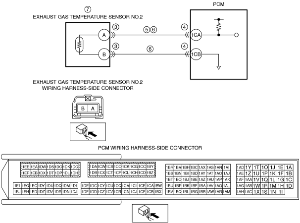
•  Exhaust gas temperature sensor No.2 connector or terminals malfunction
•  PCM connector or terminals malfunction
•  Short to power supply in wiring harness between exhaust gas temperature sensor No.2 terminal A and PCM terminal 1CA
•  Open circuit in wiring harness between the following terminals:
―  Exhaust gas temperature sensor No.2 terminal A—PCM terminal 1CA
―  Exhaust gas temperature sensor No.2 terminal B—PCM terminal 1CB
•  Exhaust gas temperature sensor No.2 malfunction
•  PCM malfunction

Diagnostic Procedure

STEP

INSPECTION

ACTION

1
VERIFY FREEZE FRAME DATA (MODE 2)/SNAPSHOT DATA HAS BEEN RECORDED
•  Has the FREEZE FRAME DATA (Mode 2)/snapshot data been recorded?
Yes
Go to the next step.
No
Record the FREEZE FRAME DATA (Mode 2)/snapshot data on the repair order, then go to the next step.
2
VERIFY RELATED SERVICE INFORMATION AVAILABILITY
•  Verify related Service Information availability.
•  Is any related Service Information available?
Yes
Perform repair or diagnosis according to the available Service Information.
•  If the vehicle is not repaired, go to the next step.
No
Go to the next step.
3
INSPECT EXHAUST GAS TEMPERATURE SENSOR NO.2 CONNECTOR CONDITION
•  Switch the ignition off.
•  Disconnect the exhaust gas temperature sensor No.2 connector.
•  Inspect for poor connection (such as damaged/pulled-out pins, corrosion).
•  Is there any malfunction?
Yes
Repair or replace the connector and/or terminals, then go to Step 8.
No
Go to the next step.
4
INSPECT PCM CONNECTOR CONDITION
•  Disconnect the PCM connector.
•  Inspect for poor connection (such as damaged/pulled-out pins, corrosion).
•  Is there any malfunction?
Yes
Repair or replace the connector and/or terminals, then go to Step 8.
No
Go to the next step.
5
INSPECT EXHAUST GAS TEMPERATURE SENSOR NO.2 SIGNAL CIRCUIT FOR SHORT TO POWER SUPPLY
•  Verify that the exhaust gas temperature sensor No.2 and PCM connectors are disconnected.
•  Switch the ignition ON (engine off).
•  Measure the voltage at the exhaust gas temperature sensor No.2 terminal A (wiring harness-side).
•  Is the voltage 0 V?
Yes
Go to the next step.
No
Refer to the wiring diagram and verify whether or not there is a common connector between exhaust gas temperature sensor No.2 terminal A and PCM terminal 1CA.
If there is a common connector:
•  Determine the malfunctioning part by inspecting the common connector and the terminal for corrosion, damage, or pin disconnection, and the common wiring harness for a short to power supply.
•  Repair or replace the malfunctioning part.
If there is no common connector:
•  Repair or replace the wiring harness which has a short to power supply.
Go to Step 8.
6
INSPECT EXHAUST GAS TEMPERATURE SENSOR NO.2 CIRCUIT FOR OPEN CIRCUIT
•  Verify that the exhaust gas temperature sensor No.2 and PCM connectors are disconnected.
•  Switch the ignition off.
•  Inspect for continuity between the following terminals (wiring harness-side):
―  Exhaust gas temperature sensor No.2 terminal A—PCM terminal 1CA
―  Exhaust gas temperature sensor No.2 terminal B—PCM terminal 1CB
•  Is there continuity?
Yes
Go to the next step.
No
Refer to the wiring diagram and verify whether or not there is a common connector between the following terminals:
•  Exhaust gas temperature sensor No.2 terminal A—PCM terminal 1CA
•  Exhaust gas temperature sensor No.2 terminal B—PCM terminal 1CB
If there is a common connector:
•  Determine the malfunctioning part by inspecting the common connector and the terminal for corrosion, damage, or pin disconnection, and the common wiring harness for an open circuit.
•  Repair or replace the malfunctioning part.
If there is no common connector:
•  Repair or replace the wiring harness which has an open circuit.
Go to Step 8.
7
INSPECT EXHAUST GAS TEMPERATURE SENSOR NO.2
•  Reconnect all disconnected connectors.
•  Inspect the exhaust gas temperature sensor No.2.
•  Is there any malfunction?
Yes
Replace the exhaust gas temperature sensor No.2, then go to the next step.
No
Go to the next step.
8
VERIFY DTC TROUBLESHOOTING COMPLETED
•  Always reconnect all disconnected connectors.
•  Clear the DTC from the PCM memory using the M-MDS.
•  Perform the Drive Mode Type B.
•  Perform the DTC Reading Procedure.
•  Is the same DTC present?
Yes
Repeat the inspection from Step 1.
•  If the malfunction recurs, replace the PCM.
Go to the next step.
No
Go to the next step.
9
VERIFY AFTER REPAIR PROCEDURE
•  Perform the “AFTER REPAIR PROCEDURE”.
•  Are any DTCs present?
Yes
Go to the applicable DTC inspection.
No
DTC troubleshooting completed.