 |
am3zzw00013589
EXHAUST GAS TEMPERATURE SENSOR REMOVAL/INSTALLATION [SKYACTIV-D 2.2]
id0140z7446400
Exhaust Gas Temperature Sensor No.1
1. Disconnect the negative battery cable. (See NEGATIVE BATTERY CABLE DISCONNECTION/CONNECTION [SKYACTIV-D 2.2].)
2. Remove the battery. (See BATTERY REMOVAL/INSTALLATION [SKYACTIV-D 2.2].)
3. Remove the air inlet pipe, air hose and turbocharger air inlet hose. (See INTAKE-AIR SYSTEM REMOVAL/INSTALLATION [SKYACTIV-D 2.2].)
4. Disconnect the exhaust gas temperature sensor No.1 connector.
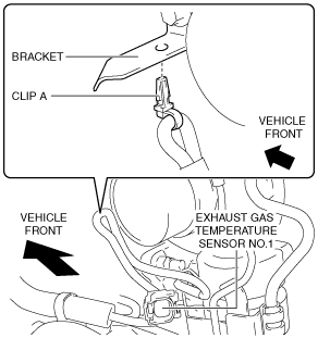
5. Remove the clip A from the bracket.
am3zzw00013589
|
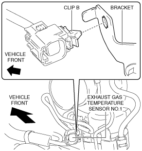
6. Remove the clip B from the bracket.
am3zzw00013590
|
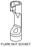
7. Remove the exhaust gas temperature sensor No.1. (See Exhaust Gas Temperature Sensor No.1 Installation Note.)
ac5wzw00004444
|
ac5wzw00008481
|
8. Install in the reverse order of removal.
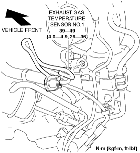
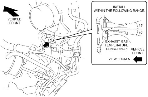
Exhaust Gas Temperature Sensor No.1 Installation Note
1. Install the exhaust gas temperature sensor No.1 shown in the figure.
am6zzw00008594
|
Exhaust Gas Temperature Sensor No.2
1. Disconnect the negative battery cable. (See NEGATIVE BATTERY CABLE DISCONNECTION/CONNECTION [SKYACTIV-D 2.2].)
2. Remove the engine cover. (See ENGINE COVER REMOVAL/INSTALLATION [SKYACTIV-D 2.2].)
3. Remove the insulator. (See TIMING CHAIN REMOVAL/INSTALLATION [SKYACTIV-D 2.2].)
4. Disconnect the exhaust gas temperature sensor No.2 connector.
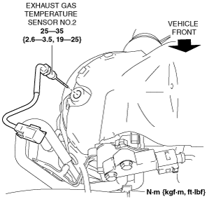
5. Remove the exhaust gas temperature sensor No.2. (See Exhaust Gas Temperature Sensor No.2 Installation Note.)
ac5wzw00004442
|
6. Install in the reverse order of removal.
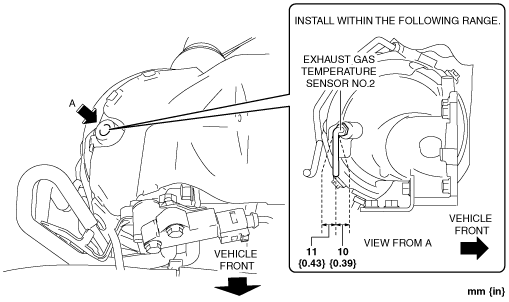
Exhaust Gas Temperature Sensor No.2 Installation Note
1. Install the exhaust gas temperature sensor No.2 shown in the figure.
am6zzw00008595
|
Exhaust Gas Temperature Sensor No.3
am6zzw00008596
|
1. Turn the steering wheel to full right lock.
2. Disconnect the negative battery cable. (See NEGATIVE BATTERY CABLE DISCONNECTION/CONNECTION [SKYACTIV-D 2.2].)
3. Lift up the vehicle.
4. Remove the front splash shield (RH). (See SPLASH SHIELD REMOVAL/INSTALLATION.)
5. Remove the plate (exhaust system). (See EXHAUST SYSTEM REMOVAL/INSTALLATION [SKYACTIV-D 2.2].)
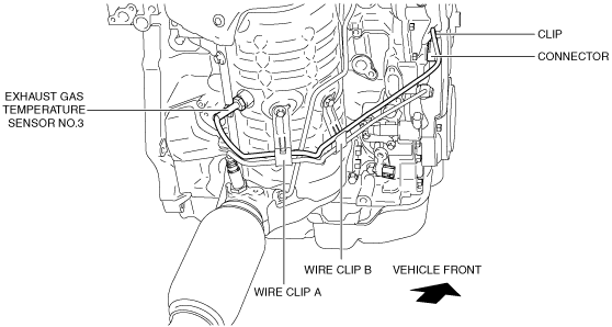
6. Disconnect the exhaust gas temperature sensor No.3 connector.
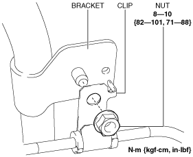
7. Remove the clip from the bracket.
ac5wzw00006396
|
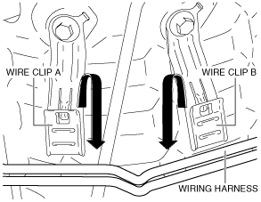
8. Remove the wiring harness from the wire clip A and B. (See Assembly of Wiring Harness to Wire Clip Note.)
ac5wzw00004448
|
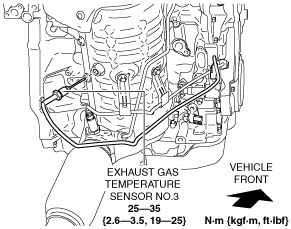
9. Remove the exhaust gas temperature sensor No.3.
am6zzw00008597
|
10. Install in the reverse order of removal.
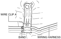
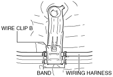
Assembly of Wiring Harness to Wire Clip Note
am6zzw00008598
|
am6zzw00008599
|