COMPRESSION INSPECTION [SKYACTIV-D 1.5]
id0110q2800300
-
Warning
-
• Hot engines and oil can cause severe burns. Be careful not to burn yourself during removal/installation of each component.
• Fuel vapor is hazardous. It can very easily ignite, causing serious injury and damage. Always keep sparks and flames away from fuel.
• Fuel line spills and leakage from the pressurized fuel system are dangerous. Fuel can ignite and cause serious injury or death, and damage to property and facilities. If fuel comes into contact with the skin and eyes it will cause irritation. To prevent this, always complete the “Fuel Line Safety Procedure”. (See
BEFORE SERVICE PRECAUTION [SKYACTIV-D 1.5].)
1. Verify that the battery is fully charged. (See BATTERY INSPECTION [SKYACTIV-D 1.5].)
-
2. Connect the M-MDS to the DLC-2.
3. Warm up the engine to the normal operating temperature.
4. Display the following PIDs using the M-MDS data monitor function. (See PCM INSPECTION [SKYACTIV-D 1.5].)
-
• RPM (engine speed)
5. Perform “Fuel Line Safety Procedures”. (See BEFORE SERVICE PRECAUTION [SKYACTIV-D 1.5].)
6. Remove the engine cover. (See ENGINE COVER REMOVAL/INSTALLATION [SKYACTIV-D 1.5].)
7. Disconnect the fuel injector connector.
8. Disconnect the fuel pressure relief valve connector.
9. Remove the EGR pipe. (See EGR PIPE REMOVAL/INSTALLATION [SKYACTIV-D 1.5].)
10. Remove the water-cooled charge air cooler reserve tank with the hose connected. (See WATER-COOLED CHARGE AIR COOLER RESERVE TANK REMOVAL/INSTALLATION [SKYACTIV-D 1.5].)
11. Remove the glow plugs. (See GLOW PLUG REMOVAL/INSTALLATION [SKYACTIV-D 1.5].)
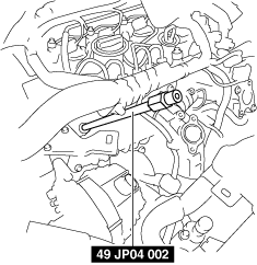
12. Install the SST using the following procedure:
- (1) Install the SST (49 JP04 002) to the glow plug installation hole.
-
- (2) Tighten the SST to the specified torque.
-
-
Tightening torque
-
15—20 N·m {1.6—2.0 kgf·m, 12—14 ft·lbf}
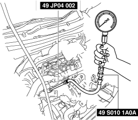
- (3) Connect the SST (49 S010 1A0A) to the SST (49 JP04 002).
-
13. Measure the compression pressure using the following procedure.
-
Note
-
• The cranking method is as follows.
MTX
-
― When the ignition switch is pressed with the clutch pedal depressed, cranking starts.
― When your foot is removed from the clutch pedal during cranking, cranking stops.
― When the ignition switch is pressed during cranking, cranking stops.
ATX
-
― When the ignition switch is pressed with the brake pedal depressed, cranking starts.
― When the ignition switch is pressed during cranking, cranking stops.
- (1) Crank the engine and measure the following values simultaneously.
-
-
• Compression pressure
• Engine speed
-
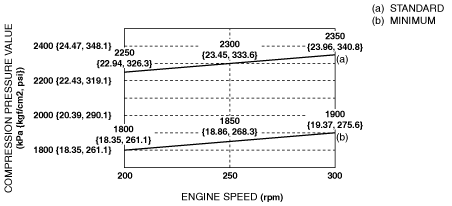
-
Standard: Refer to the graph.
Minimum: Refer to the graph.
Maximum difference between cylinders: 150 kPa {1.53 kgf/cm2, 21.8 psi}[200 rpm]
- (2) Perform Step (1) for all cylinders.
-
- (3) If a measurement is less than the minimum specification, or there is a cylinder which exceeds the specified difference between cylinders, add a small quantity of engine oil through the glow plug installation hole and perform Step (1).
-
-
• If the pressure increases by adding the engine oil, the piston ring or the cylinder surface is worn, or they are damaged. Perform overhaul servicing.
• If the pressure does not increase, valve seizure, valve attachment malfunction, or pressure leakage from the cylinder head gasket might be occurring. Perform overhaul servicing.
14. Remove the SSTs.
15. Install the glow plugs. (See GLOW PLUG REMOVAL/INSTALLATION [SKYACTIV-D 1.5].)
16. Install the water-cooled charge air cooler reserve tank. (See WATER-COOLED CHARGE AIR COOLER RESERVE TANK REMOVAL/INSTALLATION [SKYACTIV-D 1.5].)
17. Install the EGR pipe. (See EGR PIPE REMOVAL/INSTALLATION [SKYACTIV-D 1.5].)
18. Connect the fuel pressure relief valve connector.
19. Connect the fuel injector connector.
20. Install the engine cover. (See ENGINE COVER REMOVAL/INSTALLATION [SKYACTIV-D 1.5].)