 |
am3zzw00020888
CLUTCH UNIT REMOVAL/INSTALLATION [D66M-R]
id0510md157200
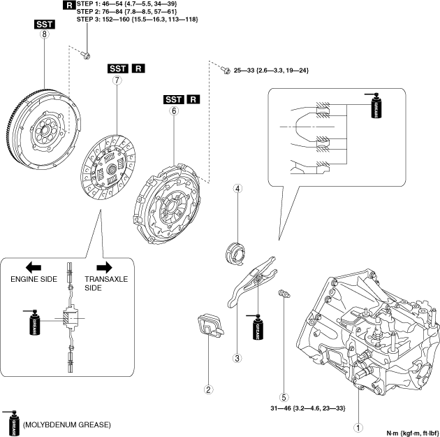
1. Remove in the order indicated in the table.
2. Install in the reverse order of removal.
am3zzw00020888
|
|
1
|
Manual transaxle
|
|
2
|
Boot
|
|
3
|
Clutch release fork
|
|
4
|
Clutch release collar
|
|
5
|
Pivot pin
|
|
6
|
Clutch cover
|
|
7
|
Clutch disc
|
|
8
|
Dual-mass flywheel
|
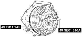
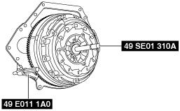
Clutch Cover And Clutch Disc Removal Note
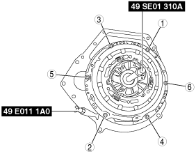
1. Install the SSTs (49 E011 1A0, 49 SE01 310A).
ac5wzw00005659
|
2. Loosen each bolt one turn at a time in a crisscross pattern until spring tension is released.
3. Remove the clutch cover and clutch disc.
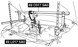
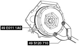
Dual-mass Flywheel Removal Note
1. Verify that the SSTs (49 C017 5A0, 49 L017 5A0) support the engine securely.
ac5wzw00005829
|
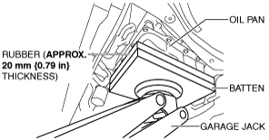
2. Support the engine using a garage jack.
am3zzw00020889
|
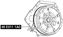
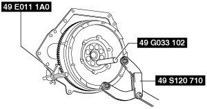
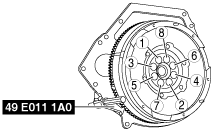
3. Lock the dual-mass flywheel against rotation using the SST (49 E011 1A0).
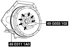
4. Loosen the lock bolts uniformly and gradually in the order shown in the figure, and remove them.
ac5wzw00005660
|
am3zzw00020890
|
am3zzw00020891
|
5. Remove the dual-mass flywheel.
6. Inspect for oil leakage from the crankshaft rear oil seal.
Dual-mass Flywheel Installation Note
1. Verify that the SSTs (49 C017 5A0, 49 L017 5A0) support the engine securely.
ac5wzw00005829
|
2. Support the engine using a garage jack.
am3zzw00020889
|
3. Clean the dual-mass flywheel.
4. Clean the crankshaft thread holes.
5. Install the dual-mass flywheel to the crankshaft.
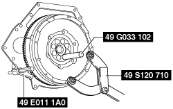
6. Lock the dual-mass flywheel against rotation using the SST (49 E011 1A0).
7. Temporarily tighten the new lock bolts.
am6zzw00011777
|
am3zzw00020892
|
8. Tighten the lock bolts completely in the order shown in the figure in the following 3 steps.
ac5wzw00005664
|
Clutch Disc Installation Note
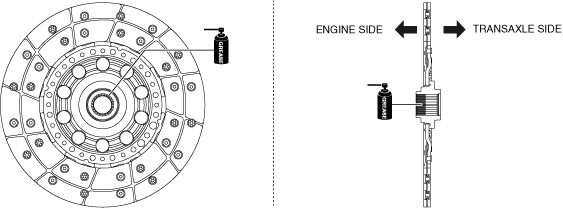
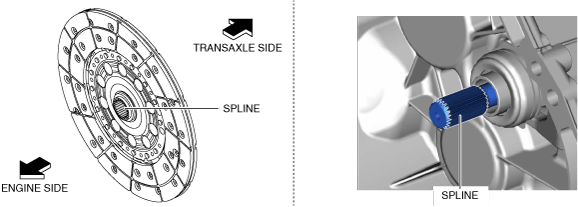
1. Clean the splines of the new clutch disc and the primary shaft with a brush.
2. Apply grease to the spline (engine side) of the clutch disc.
am3zzw00020893
|
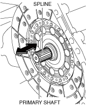
3. Insert the clutch disc into the primary shaft and wipe off the excess grease protruding from the spline.
am3zzw00020894
|
4. Slide the clutch disc three times in the directions of the arrows shown in the figure to engage to grease.
5. Remove the clutch disc from the primary shaft and wipe off the excess grease protruding from the spline.
am3zzw00020895
|
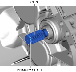
6. Verify that grease has been lightly applied to the clutch disc and the spline of the primary shaft.
am3zzw00020896
|
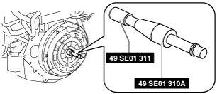
7. Install the SST (49 SE01 311) to the SST (49 SE01 310A) as shown in the figure.
am3zzw00015609
|
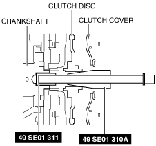
8. Insert the end of the assembled SSTs into the crankshaft end, align the center of the clutch disc with the center of the flywheel, and secure them using the SSTs as shown in the figure.
am3zzw00020897
|
Clutch Cover Installation Note
1. Install the new clutch cover while aligning the guide pins.
2. Install the SST (49 E011 1A0).
ac5wzw00005666
|
3. Tighten the bolts in the order shown in the figure.
ac5wzw00005667
|
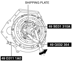
4. While holding the SST (49 SE01 310A) so that the center position of the clutch disc does not deviate, remove the shipping plate using the SST (49 G032 354).
ac5wzw00005909
|
5. Dispose of the shipping plate after removal.
6. Remove the SSTs.