MANUAL TRANSAXLE REMOVAL/INSTALLATION [D66M-R]
id0515mb160000
Removal
1. Disconnect the negative battery cable. (See NEGATIVE BATTERY CABLE DISCONNECTION/CONNECTION [SKYACTIV-D 2.2].)
2. Remove the engine cover. (See ENGINE COVER REMOVAL/INSTALLATION [SKYACTIV-D 2.2].)
3. Remove the front under cover No.2. (See FRONT UNDER COVER No.2 REMOVAL/INSTALLATION.)
4. Remove the front under cover No.1. (See FRONT UNDER COVER No.1 REMOVAL/INSTALLATION.)
5. Remove the splash shield. (See SPLASH SHIELD REMOVAL/INSTALLATION.)
6. Drain the manual transaxle oil. (See MANUAL TRANSAXLE OIL REPLACEMENT [D66M-R].)
7. Disconnect and/or remove the following parts in the engine compartment.
- (1) Remove the air cleaner and air hose as a single unit. (See INTAKE-AIR SYSTEM REMOVAL/INSTALLATION [SKYACTIV-D 2.2].)
-
- (2) Remove the battery and battery tray. (See BATTERY REMOVAL/INSTALLATION [SKYACTIV-D 2.2].)
-
- (3) Disconnect the control cable from the MTX. (See MANUAL TRANSAXLE SHIFT MECHANISM REMOVAL/INSTALLATION [D66M-R].)
-
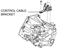
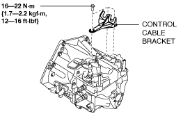
- (4) Remove the control cable bracket from the MTX.
-
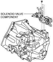
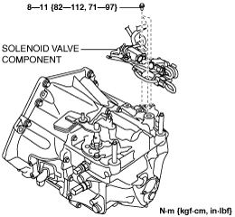
- (5) Remove the solenoid valve component from the MTX with the hose still connected, and set it out of the way.
-
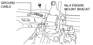
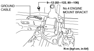
- (6) Remove the bolt shown in the figure, and set the ground cable aside.
-
- (7) Drain the engine coolant. (See ENGINE COOLANT REPLACEMENT [SKYACTIV-D 2.2].)
-
- (8) Remove the EGR cooler. (See EGR COOLER REMOVAL/INSTALLATION [SKYACTIV-D 2.2].)
-
- (9) Disconnect the neutral switch connector from the MTX. (See NEUTRAL SWITCH REMOVAL/INSTALLATION [D66M-R].)
-
- (10) Disconnect the back-up light switch connector from the MTX. (See BACK-UP LIGHT SWITCH REMOVAL/INSTALLATION [D66M-R].)
-
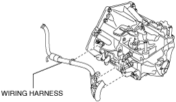
- (11) Disconnect the wiring harness from the MTX, and set the wiring harness aside.
-
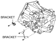
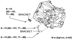
- (12) Remove the brackets from the MTX.
-
8. Disconnect and/or remove the following parts related to the suspension and axle.
- (1) Remove the front tires. (See GENERAL PROCEDURES (FRONT AND REAR AXLES).)
-
- (2) Disconnect the clip securing the brake hose from the shock absorber. (See BRAKE HOSE (FRONT) REMOVAL/INSTALLATION.)
-
- (3) Disconnect the ABS wheel-speed sensors from the steering knuckles. (See FRONT ABS WHEEL-SPEED SENSOR REMOVAL/INSTALLATION.)
-
- (4) Disconnect the tie-rod end ball joints from the steering knuckles. (See FRONT CROSSMEMBER REMOVAL/INSTALLATION [SKYACTIV-D 1.5, SKYACTIV-D 2.2].)
-
- (5) Disconnect the stabilizer control links from the stabilizer. (See FRONT STABILIZER REMOVAL/INSTALLATION.)
-
- (6) Disconnect the front lower arms from the steering knuckles. (See FRONT CROSSMEMBER REMOVAL/INSTALLATION [SKYACTIV-D 1.5, SKYACTIV-D 2.2].)
-
- (7) Disconnect the drive shaft (LH) from the MTX. (See FRONT DRIVE SHAFT REMOVAL/INSTALLATION.)
-
- (8) Disconnect the drive shaft (RH) from the MTX. (See FRONT DRIVE SHAFT REMOVAL/INSTALLATION.)
-
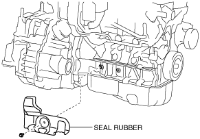
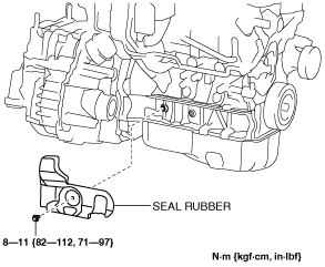
- (9) Remove the seal rubber.
-
9. Disconnect and/or remove the following parts from the underside of the vehicle.
- (1) Remove the clutch release cylinder with the clutch pipe still connected and set it out of the way. (See CLUTCH RELEASE CYLINDER REMOVAL/INSTALLATION [D66M-R].)
-
- (2) Disconnect the clutch pipe from the front frame. (See CLUTCH PIPE AND HOSE REMOVAL/INSTALLATION [D66M-R].)
-
- (3) Remove the starter. (See STARTER REMOVAL/INSTALLATION [SKYACTIV-D 2.2].)
-
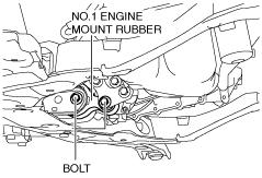
- (4) Remove the front crossmember component and No.1 engine mount rubber as a single unit. (See FRONT CROSSMEMBER REMOVAL/INSTALLATION [SKYACTIV-D 1.5, SKYACTIV-D 2.2].)
-
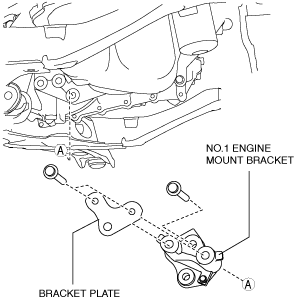
- (5) Remove the bracket plate and No.1 engine mount bracket from the MTX.
-
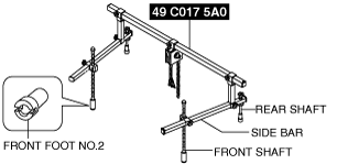
10. Install the SST using the following procedure.
-
Caution
-
• Refer to the SST instruction manual for the basic handing procedure.
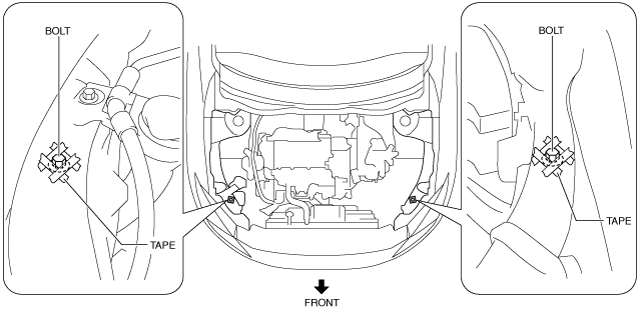
- (1) Install one front foot No.2 to each of the left and right front shafts of the SST.
-
- (2) Protect the positions shown in the figure using tape.
-
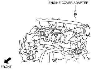
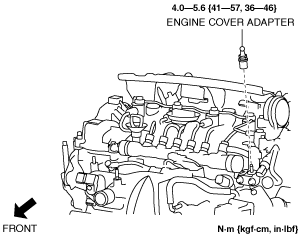
- (3) Remove the engine cover adapter.
-
- (4) Install the SST to the position shown in the figure using the following bolt and washer.
-
-
Bolt: part number 99794 1025 or an M10 × 1.25, length 25 mm {0.98 in}
Washer: approx. 3 mm {0.1 in} thickness
-
Tightening torque
-
38—51 N·m {3.9—5.2 kgf·m, 29—37 ft·lbf}
- (5) Install the SST to the position shown in the figure using the following bolt.
-
-
Bolt: part number 99794 1025 or an M10 × 1.25, length 25 mm {0.98 in}
-
Tightening torque
-
38—51 N·m {3.9—5.2 kgf·m, 29—37 ft·lbf}
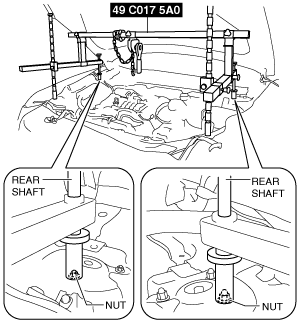
- (6) As shown in the figure, set the rear shafts of the SST to the left and right shock absorber nuts.
-
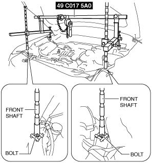
- (7) As shown in the figure, set the front shafts of the SST to the left and right bolts.
-
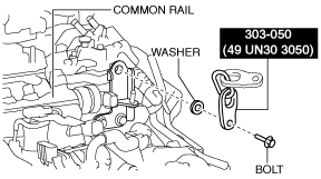
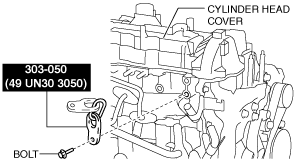
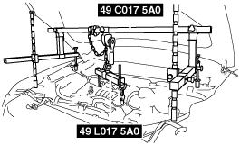
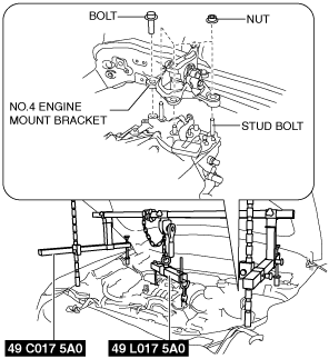
- (8) Install the SST (49 L017 5A0) to the SST (49 C017 5A0) as shown in the figure.
-
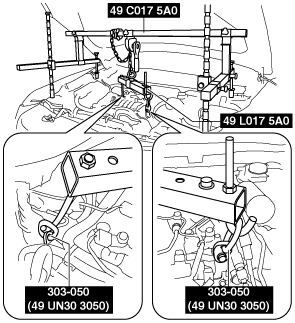
- (9) Install the SST (49 L017 5A0) to the SST (49 UN30 3050) with the hook of the SST (49 L017 5A0) facing outward.
-
- (10) Adjust the height of the left and right side bars so that they are leveled, then tighten each part of the SST.
-
- (11) Apply tension to the chain to secure the engine.
-
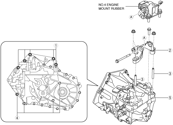
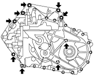
11. Remove in the order indicated in the table.
|
1
|
Transaxle mounting bolt (upper side)
|
|
2
|
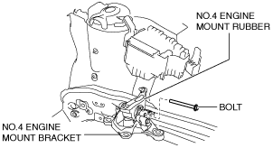
No.4 engine mount bracket
|
|
3
|
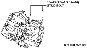
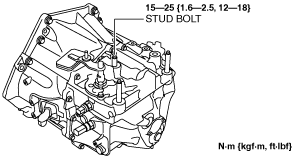
Stud bolt
|
|
4
|
Transaxle mounting bolt (lower side)
|
|
5
|
MTX
|
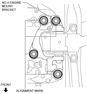
No.4 engine mount bracket removal note
-
Caution
-
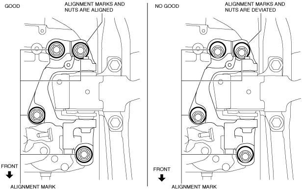
• A slot has been adopted for the No.4 engine mount bracket installation hole. If the No.4 engine mount bracket is deviated from the original position when installing the No.4 engine mount, engine noise or vibration could increase. When removing the No.4 engine mount, place alignment marks on the No.4 engine mount bracket so that they can be assembled to the same positions as before removal.
1. Place alignment marks on the locations shown in the figure so that they can be assembled to the same positions as before removal.
-
Note
-
• Paint so that the outline of the nut is framed on the bracket side.
2. Remove the No.4 engine mount bracket.
Transaxle mounting bolt removal note
-
Warning
-
• Remove the MTX carefully, holding it steady. If the MTX falls it could be damaged or cause injury.
1. Adjust the SST and lean the engine toward the MTX.
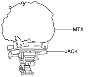
2. Support the MTX on a jack.
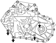
3. Remove the transaxle mounting bolts (lower side).
4. Remove the MTX.
Installation
-
Warning
-
• Install the MTX carefully, holding it steady. If the MTX falls it could be damaged or cause injury.
1. Set the MTX on a jack and lift into place.
2. Install the MTX to the engine, and tighten the transaxle mounting bolts.
-
Tightening torque
-
38—52 N·m {3.9—5.3 kgf·m, 29—38 ft·lbf}
3. Install the stud bolts to the MTX.
4. Tighten the stud bolt for the MTX.
5. Install the No.4 engine mount bracket to No.4 engine mount rubber, and temporarily tighten the installation bolt.
6. Pull up the MTX using the SSTs, pass the MTX stud bolts through the No.4 engine mount bracket, and temporarily tighten the No.4 engine mount installation nuts and bolt.
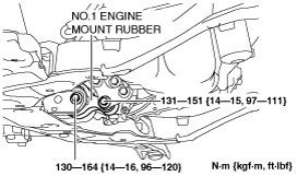
7. Install the No.1 engine mount bracket and bracket plate to the MTX, and temporarily tighten the installation bolts.
8. Install the front crossmember component and No.1 engine mount rubber as a single unit. (See FRONT CROSSMEMBER REMOVAL/INSTALLATION [SKYACTIV-D 1.5, SKYACTIV-D 2.2].)
9. Temporarily tighten the No.1 engine mount rubber installation bolts.
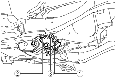
10. Align the alignment marks on the No.4 engine mount bracket and nuts, and temporarily tighten the nuts shown in the figure.
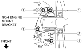
11. Tighten the No.4 engine mount bracket installation nuts and bolt in the order shown in the figure.
|
No.
|
Tightening torque
|
|
1
|
92—116 N·m {9.4—11 kgf·m, 68—85 ft·lbf}
|
|
2
|
81—99 N·m {8.3—10 kgf·m, 60—73 ft·lbf}
|
12. Remove the SST (49 C017 5A0, 49 L017 5A0).
13. Tighten the No.1 engine mount bracket and bracket plate installation bolts in the order shown in the figure.
-
Tightening torque
-
131—153 N·m {14—15 kgf·m, 97—112 ft·lbf}
14. Tighten the No.1 engine mount rubber installation bolts.
15. Connect and/or Install the following parts to the underside of the vehicle.
- (1) Install the starter. (See STARTER REMOVAL/INSTALLATION [SKYACTIV-D 2.2].)
-
- (2) Install the clutch release cylinder to the MTX. (See CLUTCH RELEASE CYLINDER REMOVAL/INSTALLATION [D66M-R].)
-
16. Connect and/or Install the following parts related to the suspension and axle.
- (1) Install the seal rubber.
-
- (2) Connect the drive shaft (RH) to the MTX. (See FRONT DRIVE SHAFT REMOVAL/INSTALLATION.)
-
- (3) Connect the drive shaft (LH) to the MTX. (See FRONT DRIVE SHAFT REMOVAL/INSTALLATION.)
-
- (4) Connect the front lower arms to the steering knuckles. (See FRONT CROSSMEMBER REMOVAL/INSTALLATION [SKYACTIV-D 1.5, SKYACTIV-D 2.2].)
-
- (5) Connect the stabilizer control links to the stabilizer. (See FRONT STABILIZER REMOVAL/INSTALLATION.)
-
- (6) Connect the tie-rod end ball joints to the steering knuckles. (See FRONT CROSSMEMBER REMOVAL/INSTALLATION [SKYACTIV-D 1.5, SKYACTIV-D 2.2].)
-
- (7) Connect the ABS wheel-speed sensors to the steering knuckles. (See FRONT ABS WHEEL-SPEED SENSOR REMOVAL/INSTALLATION.)
-
- (8) Connect the clip securing the brake hose to the shock absorber. (See BRAKE HOSE (FRONT) REMOVAL/INSTALLATION.)
-
- (9) Install the front tires. (See GENERAL PROCEDURES (FRONT AND REAR AXLES).)
-
17. Connect and/or install the following parts in the engine compartment.
- (1) Install the engine cover adapter.
-
- (2) Install the brackets to the MTX.
-
- (3) Connect the wiring harness to the MTX.
-
- (4) Connect the back-up light switch connector.(See BACK-UP LIGHT SWITCH REMOVAL/INSTALLATION [D66M-R].)
-
- (5) Connect the neutral switch connector. (See NEUTRAL SWITCH REMOVAL/INSTALLATION [D66M-R].)
-
- (6) Install the EGR cooler. (See EGR COOLER REMOVAL/INSTALLATION [SKYACTIV-D 2.2].)
-
- (7) Connect the ground cable to the No.4 engine mount bracket.
-
- (8) Install the solenoid valve component to the MTX.
-
- (9) Install the control cable bracket to the MTX.
-
- (10) Connect the control cable to the MTX. (See MANUAL TRANSAXLE SHIFT MECHANISM REMOVAL/INSTALLATION [D66M-R].)
-
- (11) Install the battery tray and battery. (See BATTERY REMOVAL/INSTALLATION [SKYACTIV-D 2.2].)
-
- (12) Install the air cleaner and air hose as a single unit. (See INTAKE-AIR SYSTEM REMOVAL/INSTALLATION [SKYACTIV-D 2.2].)
-
18. Install the splash shield. (See SPLASH SHIELD REMOVAL/INSTALLATION.)
19. Install the front under cover No.1. (See FRONT UNDER COVER No.1 REMOVAL/INSTALLATION.)
20. Refill the engine coolant. (See ENGINE COOLANT REPLACEMENT [SKYACTIV-D 2.2].)
21. Add the specified amount of specified manual transaxle oil. (See MANUAL TRANSAXLE OIL REPLACEMENT [D66M-R].)
22. Install the front under cover No.2. (See FRONT UNDER COVER No.2 REMOVAL/INSTALLATION.)
23. Connect the negative battery cable. (See NEGATIVE BATTERY CABLE DISCONNECTION/CONNECTION [SKYACTIV-D 2.2].)
24. Install the engine cover. (See ENGINE COVER REMOVAL/INSTALLATION [SKYACTIV-D 2.2].)
25. If the MTX is overhauled, perform the “INSPECTION AFTER MANUAL TRANSAXLE OVERHAUL”. (See INSPECTION AFTER MANUAL TRANSAXLE OVERHAUL [D66M-R].)