OIL PRESSURE SWITCH REPLACEMENT [CW6A-EL]
id0517l1112700
-
Warning
-
• A hot transaxle and ATF can cause severe burns. Turn off the engine and wait until they are cool.
• Always wear protective eye wear when using the air compressor. If the air compressor is used, any particles of dirt or sludge could spatter and get into the eyes.
-
Caution
-
• Do not apply excessive force to the coupler component wiring harness.
• Be careful that the edge of the oil pressure switch and the ATF temperature sensor bracket does not damage the insulation of the coupler component wiring harness or the surrounding parts. If the insulation of the wiring harness is damaged, replace the coupler component. (See
COUPLER COMPONENT REMOVAL/INSTALLATION [CW6A-EL].)
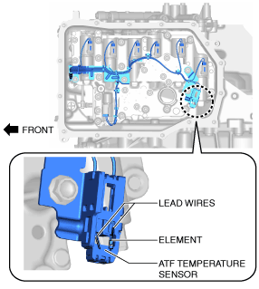
• Touching the ATF temperature sensor element or the lead wires by hand may cause a malfunction. When handling the coupler component, do not touch the ATF temperature sensor element or the lead wires.
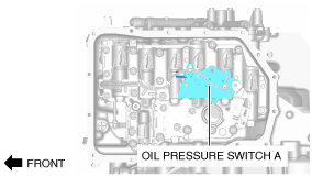
Oil Pressure Switch A
1. Select the selector lever to P position.
2. Disconnect the negative battery cable. (See NEGATIVE BATTERY CABLE DISCONNECTION/CONNECTION [SKYACTIV-G 1.5, SKYACTIV-G 2.0, SKYACTIV-G 2.5].)
3. Remove the front under cover No.2. (See FRONT UNDER COVER No.2 REMOVAL/INSTALLATION.)
4. Clean the transaxle exterior throughout with a steam cleaner or cleaning solvents.
5. Drain the ATF. (See AUTOMATIC TRANSAXLE FLUID (ATF) REPLACEMENT [CW6A-EL].)
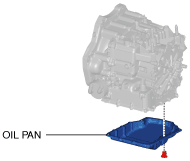
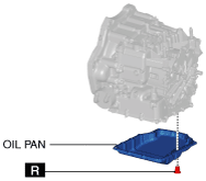
6. Remove the oil pan.
-
Note
-
• Always use new oil pan installation bolts when re-installing the oil pan because the oil pan installation bolts cannot be reused.
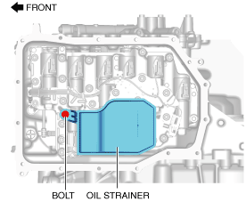
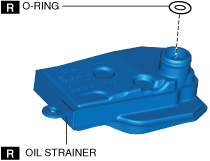
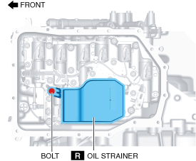
7. Remove the oil strainer.
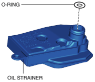
8. Remove the oil strainer O-rings.
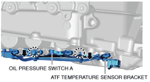
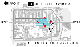
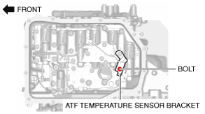
9. Remove the bolts shown in the figure.
10. Move oil pressure switch A and the ATF temperature sensor bracket in the direction of the arrow to assure a clearance to insert the tool.
-
Caution
-
• Support oil pressure switch A using a hand so as not to apply excessive force to the coupler component wiring harness.
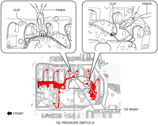
11. Using pliers, detach the tie wrap clips secured to oil pressure switch A.
-
Caution
-
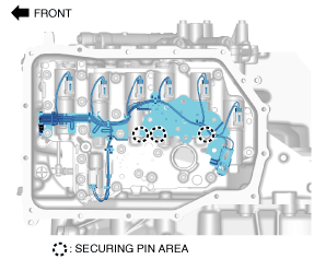
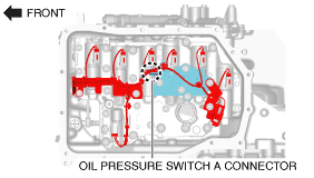
• The pins for securing the solenoid valves are located in the area circled with a dotted line, and they may drop down and be lost during coupler component removal. When removing the coupler component, be careful not to drop the pins for securing the solenoid valves, and if they do drop, be careful that they do not got lost.
• Never change the shift solenoid assembly position. If the assembly position is changed, it may cause a malfunction.
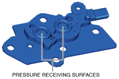
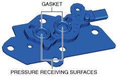
• Be careful not to allow foreign matter to get on the pressure receiving surfaces of oil pressure switch A.
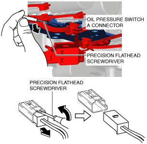
12. Insert a precision flathead screwdriver and move it in the direction of the arrow to disconnect the oil pressure switch A connector as shown in the figure.
-
Caution
-
• Set the coupler component wiring harness aside using the precision flathead screwdriver so as not to damage the wiring harness, then disconnect the oil pressure switch A connector.
• Do not scratch the oil pressure switch A connector with the precision flathead screwdriver.
• When disconnecting connectors, grasp the connectors, not the wiring harnesses. Otherwise, the wiring harnesses may be pulled out of the connector causing poor contact.
13. Remove the oil pressure switch A.
14. Install new oil pressure switch A using the bolts shown in the figure.
-
Caution
-
• Do not damage the gaskets and pressure receiving surfaces of oil pressure switch A.
-
Note
-
• Use the bolt indicated by a dotted line to tighten the ATF temperature sensor bracket together with oil pressure switch A.
-
Tightening torque
-
9—10 N·m {92—101 kgf·cm, 80—88 in·lbf}
15. Install the ATF temperature sensor bracket using the bolts shown in the figure.
-
Tightening torque
-
9—10 N·m {92—101 kgf·cm, 80—88 in·lbf}
16. Connect the oil pressure switch A connector.
-
Caution
-
• Insert the connector until a click is heard.
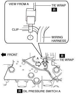
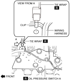
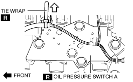
17. Using the following procedure, replace the tie wraps (2 locations) secured to oil pressure switch A.
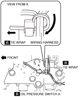
- (1) Assemble a new tie wrap to oil pressure switch A.
-
-
Caution
-
• Assemble the tie wrap in the direction shown in the figure.
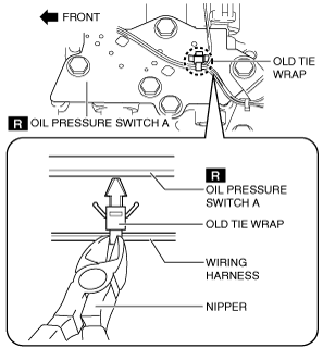
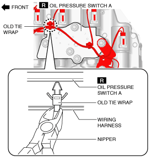
- (2) Using nippers, cut and remove the old tie wrap.
-
-
Caution
-
• Collect and dispose of the cut tie wrap and its fragments securely.
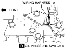
- (3) Route the wiring harness shown in the figure so that it is positioned on the vehicle front side from dotted line A (oil pressure switch A end).
-
-
Caution
-
• Route the wiring harness so that it does not contact the surrounding parts.
• Route the wiring harness so that it is not bent or twisted.
• Be careful not to pull the wiring harness excessively.
- (4) Bundle the coupler component wiring harness using a tie wrap and secure it.
-
-
Caution
-
• Make sure to bundle all wiring harnesses.
- (5) Pull the end of the tie wrap to bundle tightly.
-
- (6) Hold the tie wrap and the coupler component wiring harness in each hand, then move the tie wrap left and right and verify that the tie wrap and the wiring harness do not slide.
-
-
Caution
-
• Be careful not to move the tie wrap with excessive force.
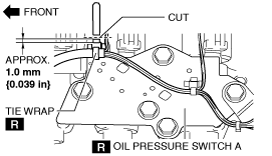
- (7) Cut the tie wrap at the position shown in the figure.
-
-
Caution
-
• Collect and dispose of the cut tie wrap and its fragments securely.
- (8) Pull the tie wrap lightly and verify that the tie wrap is securely assembled to oil pressure switch A.
-
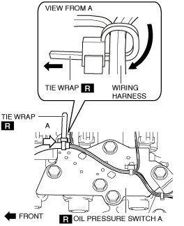
- (9) Assemble a new tie wrap to oil pressure switch A.
-
-
Caution
-
• Assemble the tie wrap in the direction shown in the figure.
- (10) Using nippers, cut and remove the old tie wrap.
-
-
Caution
-
• Collect and dispose of the cut tie wrap and its fragments securely.
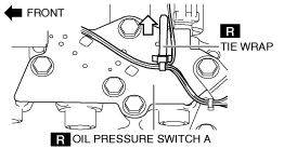
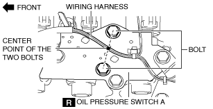
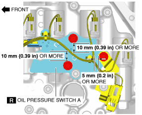
- (11) Route the wiring harness shown in the figure so that it runs on the center point of the two bolts.
-
-
Caution
-
• Route the wiring harness so that it does not contact the surrounding parts.
• Route the wiring harness so that it is not bent or twisted.
• Be careful not to pull the wiring harness excessively.
- (12) Bundle the coupler component wiring harness using a tie wrap and secure it.
-
-
Caution
-
• Make sure to bundle all wiring harnesses.
- (13) Pull the end of the tie wrap to bundle tightly.
-
- (14) Hold the tie wrap and the coupler component wiring harness in each hand, then move the tie wrap left and right and verify that the tie wrap and the wiring harness do not slide.
-
-
Caution
-
• Be careful not to move the tie wrap with excessive force.
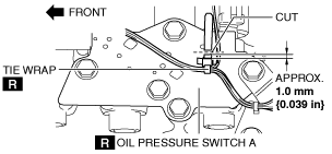
- (15) Cut the tie wrap at the position shown in the figure.
-
-
Caution
-
• Collect and dispose of the cut tie wrap and its fragments securely.
- (16) Pull the tie wrap lightly and verify that the tie wrap is securely assembled to oil pressure switch A.
-
- (17) Measure the distances between the coupler component wiring harness and the bolt flange and verify that the distances are assured as shown in the figure.
-
18. Install the new oil strainer O-rings.
19. Install the oil strainer.
-
Tightening torque
-
9—10 N·m {92—101 kgf·cm, 80—88 in·lbf}
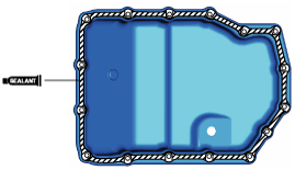
20. Apply a light coat of silicone sealant (TB1217E or equivalent) to the contact surfaces of the oil pan and transaxle case.
-
Caution
-
• Clean any remaining silicone sealant on the contact surface of the transaxle case and oil pan, and degrease the sealant area. Otherwise, oil could leak.
21. Install the oil pan with new bolts before the applied sealant starts to harden.
-
Tightening torque
-
8—10 N·m {82—101 kgf·cm, 71—88 in·lbf}
22. Add the ATF. (See AUTOMATIC TRANSAXLE FLUID (ATF) REPLACEMENT [CW6A-EL].)
23. Connect the negative battery cable. (See NEGATIVE BATTERY CABLE DISCONNECTION/CONNECTION [SKYACTIV-G 1.5, SKYACTIV-G 2.0, SKYACTIV-G 2.5].)
24. Perform the “Initial Learning”. (See INITIAL LEARNING [CW6A-EL].)
25. Perform the “Mechanical System Test”. (See MECHANICAL SYSTEM TEST [CW6A-EL].)
26. Install the front under cover No.2. (See FRONT UNDER COVER No.2 REMOVAL/INSTALLATION.)
Oil Pressure Switch B
1. Disconnect the negative battery cable. (See NEGATIVE BATTERY CABLE DISCONNECTION/CONNECTION [SKYACTIV-G 1.5, SKYACTIV-G 2.0, SKYACTIV-G 2.5].)
2. Remove the front under cover No.2. (See FRONT UNDER COVER No.2 REMOVAL/INSTALLATION.)
3. Clean the transaxle exterior throughout with a steam cleaner or cleaning solvents.
4. Drain the ATF. (See AUTOMATIC TRANSAXLE FLUID (ATF) REPLACEMENT [CW6A-EL].)
5. Remove the oil pan.
-
Note
-
• Always use new oil pan installation bolts when re-installing the oil pan because the oil pan installation bolts cannot be reused.
6. Remove the oil strainer.
7. Remove the oil strainer O-rings.
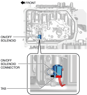
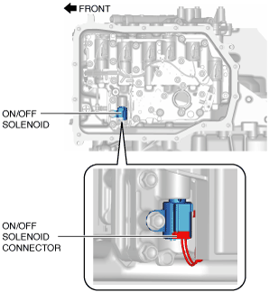
8. Release the ON/OFF solenoid connector tab using a finger and disconnect the ON/OFF solenoid connector.
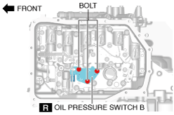
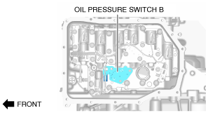
9. Remove the bolts shown in the figure.
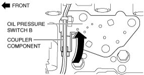
10. Move oil pressure switch B in the direction of the arrow to assure a clearance to insert the tool.
-
Caution
-
• Support oil pressure switch B using a hand so as not to apply excessive force to the coupler component wiring harness.
11. Using pliers, detach the tie wrap clips secured to oil pressure switch B.
-
Caution
-
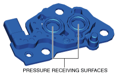
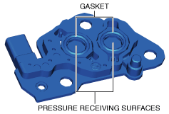
• Be careful not to allow foreign matter to get on the pressure receiving surfaces of oil pressure switch B.
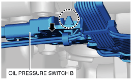
12. Rotate oil pressure switch B and the coupler component 90 degrees in the direction shown in the figure.
-
Note
-
• When disconnecting the oil pressure switch B connector, do not apply excessive force to the wiring harness.
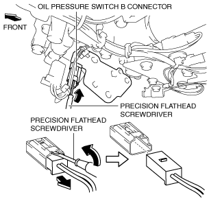
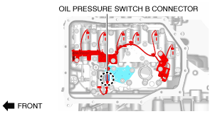
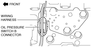
13. Insert a precision flathead screwdriver and move it in the direction of the arrow to disconnect the oil pressure switch B connector as shown in the figure.
-
Caution
-
• Set the coupler component wiring harness aside using the precision flathead screwdriver so as not to damage the wiring harness, then disconnect the oil pressure switch B connector.
• Do not scratch the oil pressure switch B connector with the precision flathead screwdriver.
• When disconnecting connectors, grasp the connectors, not the wiring harnesses. Otherwise, the wiring harnesses may be pulled out of the connector causing poor contact.
14. Remove the oil pressure switch B.
15. Install new oil pressure switch B using the bolts shown in the figure.
-
Caution
-
• Do not damage the gaskets and pressure receiving surfaces of oil pressure switch B.
-
Tightening torque
-
9—10 N·m {92—101 kgf·cm, 80—88 in·lbf}
16. Connect the oil pressure switch B connector.
-
Caution
-
• Insert the connector until a click is heard.
17. Connect the ON/OFF solenoid connector.
-
Caution
-
• Insert the connector until a click is heard.
18. Using the following procedure, replace the tie wrap secured to oil pressure switch B.
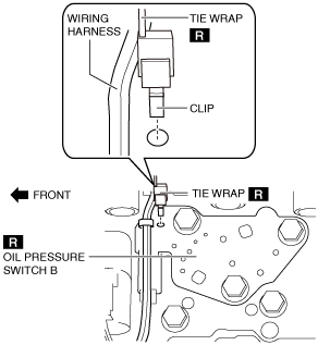
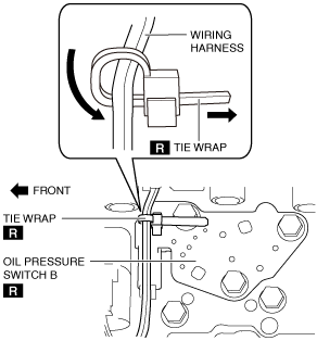
- (1) Assemble a new tie wrap to oil pressure switch B.
-
-
Caution
-
• Assemble the tie wrap in the direction shown in the figure.
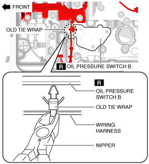
- (2) Using nippers, cut and remove the old tie wrap.
-
-
Caution
-
• Collect and dispose of the cut tie wrap and its fragments securely.
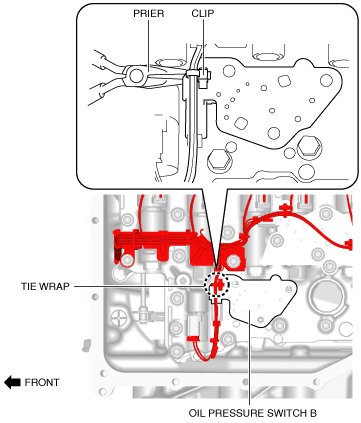
- (3) Route the wiring harness shown in the figure so that it runs straight on the oil pressure switch B connector.
-
-
Caution
-
• Route the wiring harness so that it does not contact the surrounding parts.
• Route the wiring harness so that it is not bent or twisted.
• Be careful not to pull the wiring harness excessively.
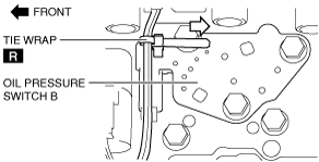
- (4) Bundle the coupler component wiring harness using a tie wrap and secure it.
-
-
Caution
-
• Make sure to bundle all wiring harnesses.
- (5) Pull the end of the tie wrap to bundle tightly.
-
- (6) Hold the tie wrap and the coupler component wiring harness in each hand, then move the tie wrap left and right and verify that the tie wrap and the wiring harness do not slide.
-
-
Caution
-
• Be careful not to move the tie wrap with excessive force.
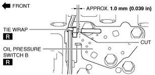
- (7) Cut the tie wrap at the position shown in the figure.
-
-
Caution
-
• Collect and dispose of the cut tie wrap and its fragments securely.
- (8) Pull the tie wrap lightly and verify that the tie wrap is securely assembled to oil pressure switch B.
-
19. Install the new oil strainer O-rings.
20. Install the oil strainer.
-
Tightening torque
-
9—10 N·m {92—101 kgf·cm, 80—88 in·lbf}
21. Apply a light coat of silicone sealant (TB1217E or equivalent) to the contact surfaces of the oil pan and transaxle case.
-
Caution
-
• Clean any remaining silicone sealant on the contact surface of the transaxle case and oil pan, and degrease the sealant area. Otherwise, oil could leak.
22. Install the oil pan with new bolts before the applied sealant starts to harden.
-
Tightening torque
-
8—10 N·m {82—101 kgf·cm, 71—88 in·lbf}
23. Add the ATF. (See AUTOMATIC TRANSAXLE FLUID (ATF) REPLACEMENT [CW6A-EL].)
24. Connect the negative battery cable. (See NEGATIVE BATTERY CABLE DISCONNECTION/CONNECTION [SKYACTIV-G 1.5, SKYACTIV-G 2.0, SKYACTIV-G 2.5].)
25. Perform the “Initial Learning”. (See INITIAL LEARNING [CW6A-EL].)
26. Perform the “Mechanical System Test”. (See MECHANICAL SYSTEM TEST [CW6A-EL].)
27. Install the front under cover No.2. (See FRONT UNDER COVER No.2 REMOVAL/INSTALLATION.)