 |
am2zzw00007715
ON/OFF SOLENOID REMOVAL/INSTALLATION [CW6A-EL]
id0517l1117100
1. Disconnect the negative battery cable. (See NEGATIVE BATTERY CABLE DISCONNECTION/CONNECTION [SKYACTIV-G 1.5, SKYACTIV-G 2.0, SKYACTIV-G 2.5].)
2. Remove the front under cover No.2. (See FRONT UNDER COVER No.2 REMOVAL/INSTALLATION.)
3. Clean the transaxle exterior throughout with a steam cleaner or cleaning solvents.
4. Drain the ATF. (See AUTOMATIC TRANSAXLE FLUID (ATF) REPLACEMENT [CW6A-EL].)
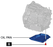
5. Remove the oil pan.
am2zzw00007715
|
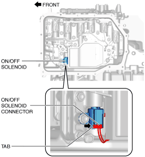
6. Release the ON/OFF solenoid connector tab using a finger and disconnect the ON/OFF solenoid connector.
am2zzw00009341
|
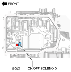
7. Remove the bolt shown in the figure and remove the ON/OFF solenoid.
am2zzw00009342
|
8. Install the ON/OFF solenoid and tighten the bolt.
am2zzw00009342
|
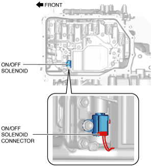
9. Connect the ON/OFF solenoid connector.
am2zzw00009343
|
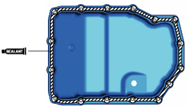
10. Apply a light coat of silicone sealant (TB1217E or equivalent) to the contact surfaces of the oil pan and transaxle case.
am2zzw00007726
|
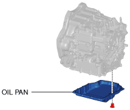
11. Install the oil pan with new bolts before the applied sealant starts to harden.
am2zzw00007727
|
12. Add the ATF. (See AUTOMATIC TRANSAXLE FLUID (ATF) REPLACEMENT [CW6A-EL].)
13. Connect the negative battery cable. (See NEGATIVE BATTERY CABLE DISCONNECTION/CONNECTION [SKYACTIV-G 1.5, SKYACTIV-G 2.0, SKYACTIV-G 2.5].)
14. Perform the “Mechanical System Test”. (See MECHANICAL SYSTEM TEST [CW6A-EL].)
15. Install the front under cover No.2. (See FRONT UNDER COVER No.2 REMOVAL/INSTALLATION.)