|
1
|
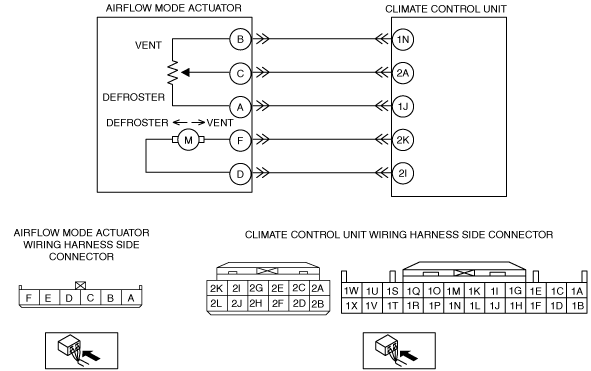
INSPECT AIRFLOW MODE ACTUATOR CONNECTOR
• Switch the ignition off.
• Disconnect the negative battery cable.
• Disconnect the airflow mode actuator connector.
• Inspect the connector and terminals (corrosion, damage, pin disconnection).
• Are the connector and terminals normal?
|
Yes
|
Go to the next step.
|
|
No
|
Repair/replace the connector or terminal.
After repair procedure, go to the next step.
|
|
2
|
INSPECT AIRFLOW MODE ACTUATOR
• Inspect the airflow mode actuator.
• Is it normal?
|
Yes
|
Go to the next step.
|
|
No
|
Replace the airflow mode actuator.
Go to the next step.
|
|
3
|
INSPECT AIRFLOW MODE MAIN LINK OPERATION
• Operate the airflow mode main link manually.
• Does the airflow mode main link operate smoothly?
|
Yes
|
Reconnect the disconnected connector, then go to the next step.
|
|
No
|
Replace the airflow mode main link, airflow mode sub link, and the airflow mode crank.
Go to the next step.
|
|
4
|
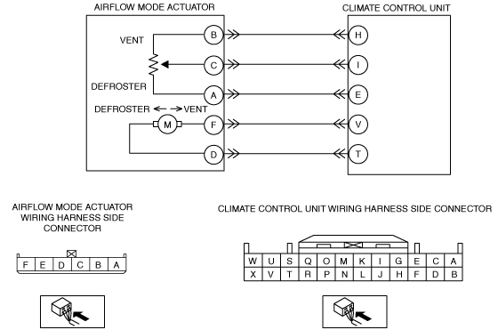
INSPECT AIRFLOW MODE ACTUATOR CIRCUIT FOR OPEN CIRCUIT OR SHORT TO GROUND
• Disconnect the climate control unit connector.
• Apply battery positive voltage and connect the ground to the climate control unit connector terminals V and T, and then inspect the airflow mode actuator.
• Does the airflow mode actuator operate?
|
Yes
|
Go to the next step.
|
|
No
|
Refer to the wiring diagram and verify whether or not there is a common connector between climate control unit terminal and airflow mode actuator terminal.
If there is a common connector:
• Determine the malfunctioning part by inspecting the common connector and the terminal for corrosion, damage, or pin disconnection, and the common wiring harness for an open circuit or short to ground.
• Repair or replace the malfunctioning part.
If there is no common connector:
• Repair or replace the wiring harness which has an open circuit or short to ground.
Go to the next step.
|
|
5
|
VERIFY CLIMATE CONTROL UNIT CONNECTOR CONDITION
• Inspect the connector and terminals (corrosion, damage, pin disconnection).
• Are the connector and terminals normal?
|
Yes
|
Go to the next step.
|
|
No
|
Repair/replace the malfunctioning vehicle wiring harness, connector, or terminal.
After repair procedure, go to the next step.
|
|
6
|
VERIFY THAT SAME DTC IS NOT OUTPUT AGAIN
• Reconnect the disconnected connectors.
• Connect the negative battery cable.
• Clear the past malfunction from memory.
• Is DTC B1086:71 output?
|
Yes
|
Repeat the inspection from Step 1.
• If the malfunction does not recur, go to the next step.
• If the malfunction recurs, replace the climate control unit.
Go to the next step.
|
|
No
|
Go to the next step.
|
|
7
|
VERIFY THAT NO OTHER DTCs ARE PRESENT
• Verify other DTCs displayed.
• Are any other DTCs output?
|
Yes
|
Perform the corresponding DTC inspection.
|
|
No
|
DTC troubleshooting completed.
|