 |
am3zzw00015146
REFRIGERANT PRESSURE SENSOR INSPECTION [FULL-AUTO AIR CONDITIONER]
id0740a1817400
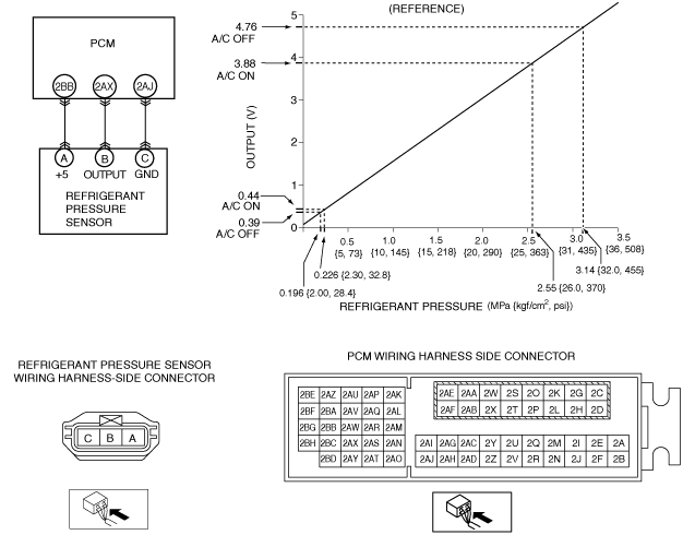
SKYACTIV-G 1.5, SKYACTIV-G 2.0, SKYACTIV-G 2.5
1. Install the manifold gauge. (See REFRIGERANT SYSTEM GENERAL PROCEDURES.)
2. Verify the high-pressure side reading of the manifold gauge.
3. Measure the terminal voltage at PCM terminal 2BB, 2AX and 2AJ.
4. Using the graph below, measure and verify the terminal voltages at 2AX.
5. Follow the PCM inspection when measuring the other terminal voltages. (See PCM INSPECTION [SKYACTIV-G 1.5, SKYACTIV-G 2.0, SKYACTIV-G 2.5].)
am3zzw00015146
|
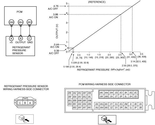
SKYACTIV-D 2.2
1. Install the manifold gauge. (See REFRIGERANT SYSTEM GENERAL PROCEDURES.)
2. Verify the high-pressure side reading of the manifold gauge.
3. Measure the terminal voltage at PCM terminal 2BB, 2BH and 2BD.
4. Using the graph below, measure and verify the terminal voltage at 2BH.
5. Follow the PCM inspection when measuring the other terminal voltages. (See PCM INSPECTION [SKYACTIV-D 2.2].)
am3zzw00015147
|
SKYACTIV-D 1.5
1. Install the manifold gauge. (See REFRIGERANT SYSTEM GENERAL PROCEDURES.)
2. Verify the high-pressure side reading of the manifold gauge.
3. Measure the terminal voltage at PCM terminal 2AR, 2BH and 2Z.
4. Using the graph below, measure and verify the terminal voltage at 2BH.
5. Follow the PCM inspection when measuring the other terminal voltages. (See PCM INSPECTION [SKYACTIV-D 1.5].)
am3zzw00017826
|
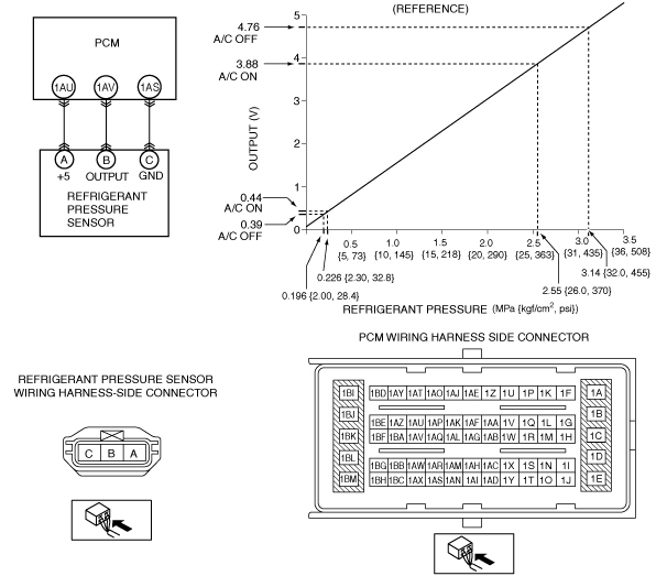
MZR 1.6
1. Install the manifold gauge. (See REFRIGERANT SYSTEM GENERAL PROCEDURES.)
2. Verify the high-pressure side reading of the manifold gauge.
3. Measure the terminal voltage at PCM terminal 1AU, 1AV and 1AS.
4. Using the graph below, measure and verify the terminal voltages at 1AV.
5. Follow the PCM inspection when measuring the other terminal voltages. (See PCM INSPECTION [MZR 1.6].)
am3zzw00015148
|