 |
am3zzw00017859
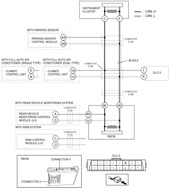
DETERMINING SHORT TO POWER SUPPLY LOCATION (MS-CAN) [SKYACTIV-G 1.5, SKYACTIV-G 2.0, SKYACTIV-G 2.5, SKYACTIV-D 2.2 (MTX)]
id100210001000
System Wiring Diagram
am3zzw00017859
|
Determination Procedure
|
Step |
Inspection |
Action |
|
|---|---|---|---|
|
1
|
INSPECT FOR SHORT TO POWER SUPPLY BETWEEN CONNECTOR C-34 AND DLC-2
• Switch the ignition off.
• Disconnect the negative battery cable.
• Disconnect connector C-34.
• Connect the negative battery cable.
• Switch the ignition ON (engine off).
• Measure the voltage at DLC-2 terminals L and K.
• Is the voltage between 1.5 — 3.5 V?
|
Yes
|
Go to the next step.
|
|
No
|
Go to Step 5.
|
||
|
2
|
INSPECT FOR SHORT TO POWER SUPPLY BETWEEN CONNECTOR C-34 AND PARKING SENSOR CONTROL MODULE
• Measure the voltage at parking sensor control module terminals AA and AB.
• Is the voltage between 1.5 — 3.5 V?
|
Yes
|
Go to Step 4.
|
|
No
|
Go to the next step.
|
||
|
3
|
INSPECT PARKING SENSOR CONTROL MODULE FOR SHORT TO POWER SUPPLY
• Switch the ignition off.
• Disconnect the negative battery cable.
• Disconnect the parking sensor control module connector.
• Connect connector C-34.
• Connect the negative battery cable.
• Switch the ignition ON (engine off).
• Measure the voltage at DLC-2 terminals L and K.
• Is the voltage between 1.5 — 3.5 V?
|
Yes
|
Replace the parking sensor control module because there is a short to the power supply in the parking sensor control module.
|
|
No
|
Repair or replace the wiring harness between the parking sensor control module and connector C-34 because the wiring harness is shorted to the power supply.
|
||
|
4
|
INSPECT INSTRUMENT CLUSTER FOR SHORT TO POWER SUPPLY
• Switch the ignition off.
• Disconnect the negative battery cable.
• Disconnect the instrument cluster connector.
• Connect connector C-34.
• Connect the negative battery cable.
• Switch the ignition ON (engine off).
• Measure the voltage at DLC-2 terminals L and K.
• Is the voltage between 1.5 — 3.5 V?
|
Yes
|
Replace the instrument cluster because there is a short to the power supply in the instrument cluster.
|
|
No
|
Repair or replace the wiring harness between the instrument cluster and connector C-34 because the wiring harness is shorted to the power supply.
|
||
|
5
|
INSPECT JB No.2 FOR SHORT TO POWER SUPPLY
• Switch the ignition off.
• Disconnect the negative battery cable.
• Connect connector C-34.
• Disconnect connector C-33.
• Connect the negative battery cable.
• Switch the ignition ON (engine off).
• Measure the voltage at instrument cluster terminals C and E.
• Is the voltage between 1.5 — 3.5 V?
|
Yes
|
Go to the next step.
|
|
No
|
Replace the JB No.2 because there is a short to the power supply in the JB No.2.
|
||
|
6
|
INSPECT FOR SHORT TO POWER SUPPLY BETWEEN CONNECTOR C-33 AND DLC-2
• Measure the voltage at DLC-2 terminals L and K.
• Is the voltage 0 V?
|
Yes
|
Go to the next step.
|
|
No
|
Repair or replace the wiring harness between the DLC-2 and connector C-33 because the wiring harness is shorted to the power supply.
|
||
|
7
|
INSPECT FOR SHORT TO POWER SUPPLY BETWEEN CONNECTOR C-33 AND CLIMATE CONTROL UNIT
• Measure the voltage at climate control unit terminals 1S and 1U. (with full-auto air conditioner (dual type))
• Measure the voltage at climate control unit terminals D and B. (with full-auto air conditioner (single type))
• Is the voltage between 1.5 — 3.5 V?
|
Yes
|
Go to Step 9.
|
|
No
|
Go to the next step.
|
||
|
8
|
INSPECT CLIMATE CONTROL UNIT FOR SHORT TO POWER SUPPLY
• Switch the ignition off.
• Disconnect the negative battery cable.
• Disconnect the climate control unit connector.
• Connect connector C-33.
• Connect the negative battery cable.
• Switch the ignition ON (engine off).
• Measure the voltage at DLC-2 terminals L and K.
• Is the voltage between 1.5 — 3.5 V?
|
Yes
|
Replace the climate control unit because there is a short to the power supply in the climate control unit.
|
|
No
|
Repair or replace the wiring harness between the climate control unit and connector C-33 because the wiring harness is shorted to the power supply.
|
||
|
9
|
INSPECT FOR SHORT TO POWER SUPPLY BETWEEN CONNECTOR C-33 AND CONNECTOR C-08
• Switch the ignition off.
• Disconnect the negative battery cable.
• Connect connector C-33.
• Disconnect the connector C-08.
• Connect the negative battery cable.
• Switch the ignition ON (engine off).
• Measure the voltage at DLC-2 terminals L and K.
• Is the voltage between 1.5 — 3.5 V?
|
Yes
|
Go to the next step.
|
|
No
|
Repair or replace the wiring harness between connector C-33 and connector C-08 because the wiring harness is shorted to the power supply.
|
||
|
10
|
INSPECT FOR SHORT TO POWER SUPPLY BETWEEN REAR VEHICLE MONITORING CONTROL MODULE (LH) / BSM CONTROL MODULE (LH) AND REAR BODY CONTROL MODULE (RBCM)
• Switch the ignition off.
• Disconnect the negative battery cable.
• Disconnect the rear body control module (RBCM) connector.
• Connect the negative battery cable.
• Switch the ignition ON (engine off).
• Measure the voltage at rear vehicle monitoring control module (LH) terminals A and D. (with rear vehicle monitoring system)
• Measure the voltage at BSM control module (LH) terminals C and D. (with BSM system)
• Is the voltage between 1.5 — 3.5 V?
|
Yes
|
Go to Step 13.
|
|
No
|
Go to the next step.
|
||
|
11
|
INSPECT FOR SHORT TO POWER SUPPLY BETWEEN REAR VEHICLE MONITORING CONTROL MODULE (LH) / BSM CONTROL MODULE (LH) AND CONNECTOR C-19
• Switch the ignition off.
• Disconnect the negative battery cable.
• Disconnect connector C-19.
• Connect the negative battery cable.
• Switch the ignition ON (engine off).
• Measure the voltage at rear vehicle monitoring control module (LH) terminals A and D. (with rear vehicle monitoring system)
• Measure the voltage at BSM control module (LH) terminals C and D. (with BSM system)
• Is the voltage between 1.5 — 3.5 V?
|
Yes
|
Repair or replace the wiring harness between the rear body control module (RBCM) and connector C-19 because the wiring harness is shorted to the power supply.
|
|
No
|
Go to the next step.
|
||
|
12
|
INSPECT REAR VEHICLE MONITORING CONTROL MODULE (LH) / BSM CONTROL MODULE (LH) FOR SHORT TO POWER SUPPLY
• Switch the ignition off.
• Disconnect the negative battery cable.
• Disconnect the rear vehicle monitoring control module (LH) connector. (with rear vehicle monitoring system)
• Disconnect the BSM control module (LH) connector. (with BSM system)
• Connect connector C-19.
• Connect the rear body control module (RBCM) connector.
• Connect connector C-08.
• Connect the negative battery cable.
• Switch the ignition ON (engine off).
• Measure the voltage at DLC-2 terminals L and K.
• Is the voltage between 1.5 — 3.5 V?
|
Yes
|
Replace the rear vehicle monitoring control module (LH) / BSM control module (LH) because there is a short to power supply in the rear vehicle monitoring control module (LH).
|
|
No
|
Repair or replace the wiring harness between the rear vehicle monitoring control module (LH) / BSM control module (LH) and connector C-19 because the wiring harness is shorted to the power supply.
|
||
|
13
|
INSPECT REAR BODY CONTROL MODULE (RBCM) FOR SHORT TO POWER SUPPLY
• Switch the ignition off.
• Disconnect the negative battery cable.
• Connect connector C-08.
• Connect the negative battery cable.
• Switch the ignition ON (engine off).
• Measure the voltage at DLC-2 terminals L and K.
• Is the voltage between 1.5 — 3.5 V?
|
Yes
|
Replace the rear body control module (RBCM) because there is a short to the power supply in the rear body control module (RBCM).
|
|
No
|
Repair or replace the wiring harness between the rear body control module (RBCM) and connector C-08 because the wiring harness is shorted to the power supply.
|
||