|
1
|
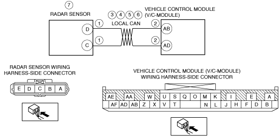
INSPECT RADAR SENSOR CONNECTOR
• Switch the ignition to off.
• Disconnect the negative battery cable.
• Remove the front bumper.
• Disconnect the radar sensor connector.
• Inspect the radar sensor connector. (Corrosion, damage, and disconnected pins)
• Is there any malfunction of the radar sensor connector?
|
Yes
|
Replace the malfunctioning part, then go to Step 8.
|
|
No
|
Go to the next step.
|
|
2
|
INSPECT VEHICLE CONTROL MODULE (V/C-MODULE) CONNECTOR
• Remove the front scuff plate (RH).
• Remove the front side trim (RH).
• Disconnect the vehicle control module (V/C-module) connector.
• Inspect the vehicle control module (V/C-module) connector. (Corrosion, damage, and disconnected pins)
• Is there any malfunction of the vehicle control module (V/C-module) connector?
|
Yes
|
Replace the malfunctioning part, then go to Step 8.
|
|
No
|
Go to the next step.
|
|
3
|
INSPECT RADAR SENSOR CIRCUIT FOR SHORT TO GROUND
• Verify that the radar sensor and vehicle control module (V/C-module) connectors are disconnected.
• Inspect for continuity between the following terminals (wiring harness-side) and body ground:
-
― Vehicle control module (V/C-module) terminal AB
― Vehicle control module (V/C-module) terminal AD
-
Note
-
• Inspect for continuity while shaking the wiring harness between the radar sensor and vehicle control module (V/C-module).
• Is there continuity?
|
Yes
|
If there is a common connector:If there is no common connector:
Refer to the wiring diagram and verify whether or not there is a common connector between radar sensor and vehicle control module (V/C-module).
• Determine the malfunctioning part by inspecting the common connector and the terminal for corrosion, damage, or pin disconnection, and the common wiring harness for a short to ground.
• Repair or replace the malfunctioning part.
• Repair or replace the wiring harness which has a short to ground.
Go to Step 8.
|
|
No
|
Go to the next step.
|
|
4
|
INSPECT RADAR SENSOR CIRCUIT FOR OPEN CIRCUIT
• Verify that the radar sensor and vehicle control module (V/C-module) connectors are disconnected.
• Inspect for continuity between the following terminals (wiring harness-side):
-
― Radar sensor terminal D—vehicle control module (V/C-module) AB
― Radar sensor terminal C—vehicle control module (V/C-module) AD
-
Note
-
• Inspect for continuity while shaking the wiring harness between the radar sensor and vehicle control module (V/C-module).
• Is there continuity?
|
Yes
|
Go to the next step.
|
|
No
|
If there is a common connector:If there is no common connector:
Refer to the wiring diagram and verify whether or not there is a common connector between radar sensor and vehicle control module (V/C-module).
• Determine the malfunctioning part by inspecting the common connector and the terminal for corrosion, damage, or pin disconnection, and the common wiring harness for an open circuit.
• Repair or replace the malfunctioning part.
• Repair or replace the wiring harness which has an open circuit.
Go to Step 8.
|
|
5
|
INSPECT RADAR SENSOR CIRCUIT FOR SHORT
• Verify that the radar sensor and vehicle control module (V/C-module) connectors are disconnected.
• Inspect between the following terminals (wiring harness-side) for continuity.
-
― Vehicle control module (V/C-module) terminals AB and AD
-
Note
-
• Inspect for continuity while shaking the wiring harness between the radar sensor and vehicle control module (V/C-module).
• Is there continuity?
|
Yes
|
If there is a common connector:If there is no common connector:
Refer to the wiring diagram and verify whether or not there is a common connector between radar sensor and vehicle control module (V/C-module).
• Determine the malfunctioning part by inspecting the common connector and the terminal for corrosion, damage, or pin disconnection, and the common wiring harness for a short circuit.
• Repair or replace the malfunctioning part.
• Repair or replace the wiring harness which has a short circuit.
Go to Step 8.
|
|
No
|
Go to the next step.
|
|
6
|
INSPECT RADAR SENSOR CIRCUIT FOR SHORT TO POWER SUPPLY
• Verify that the radar sensor and vehicle control module (V/C-module) connectors are disconnected.
• Connect the negative battery cable.
• Switch the ignition ON (engine off or on).
• Measure the voltage at the following terminals (wiring harness-side):
-
― Vehicle control module (V/C-module) terminal AB
― Vehicle control module (V/C-module) terminal AD
-
Note
-
• Measure the voltage while shaking the wiring harness between the radar sensor and vehicle control module (V/C-module).
• Is the voltage 0 V?
|
Yes
|
Go to the next step.
|
|
No
|
If there is a common connector:If there is no common connector:
Refer to the wiring diagram and verify whether or not there is a common connector between radar sensor and vehicle control module (V/C-module).
• Determine the malfunctioning part by inspecting the common connector and the terminal for corrosion, damage, or pin disconnection, and the common wiring harness for a short to power supply.
• Repair or replace the malfunctioning part.
• Repair or replace the wiring harness which has a short to power supply.
Go to Step 8.
|
|
7
|
PERFORM DTC INSPECTION FOR VEHICLE CONTROL MODULE (V/C-MODULE)
• Switch the ignition off.
• Disconnect the negative battery cable.
• Reconnect all disconnected connectors.
• Clear vehicle control module (V/C-module) DTCs using the M-MDS.
• Switch the ignition ON (engine on).
• Perform the vehicle control module (V/C-module) DTC inspection using the M-MDS.
• Is the same DTC present?
|
Yes
|
Replace the radar sensor, then go to the next step.
|
|
No
|
Go to the next step.
|
|
8
|
VERIFY THAT REPAIRS HAVE BEEN COMPLETED
• Clear vehicle control module (V/C-module) DTCs using the M-MDS.
• Switch the ignition ON (engine on).
• Perform the vehicle control module (V/C-module) DTC inspection using the M-MDS.
• Is the same DTC present?
|
Yes
|
Repeat the inspection from Step 1.
• If the malfunction recurs, replace the vehicle control module (V/C-module).
Go to the next step.
|
|
No
|
Go to the next step.
|
|
9
|
VERIFY THAT NO OTHER DTCs ARE PRESENT
• Verify other DTCs displayed.
• Are any other DTCs output?
|
Yes
|
Perform the corresponding DTC inspection.
|
|
No
|
DTC troubleshooting completed.
|