|
1
|
PERFORM DTC INSPECTION FOR PCM
• Perform the PCM DTC inspection using the M-MDS.
• Are any DTCs present?
|
Yes
|
Go to the applicable DTC inspection.
Then go to Step 5.
|
|
No
|
Go to the next step.
|
|
2
|
INSPECT FUSE
• Switch the ignition off.
• Disconnect the negative battery cable.
• Remove the C/U IG1 15 A fuse.
• Is the fuse normal?
|
Yes
|
Install the C/U IG1 15 A fuse, then go to the next step.
|
|
No
|
Replace the C/U IG1 15 A fuse, then go to Step 5.
|
|
3
|
INSPECT BATTERY
• Is the battery normal?
|
Yes
|
Go to the next step.
|
|
No
|
Replace/charge the battery, then go to Step 5.
|
|
4
|
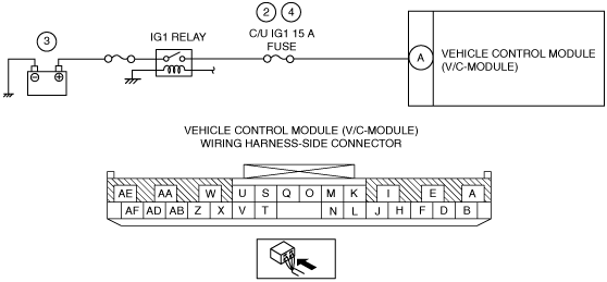
INSPECT WIRING HARNESS BETWEEN VEHICLE CONTROL MODULE (V/C-MODULE) AND IG1 RELAY
• Remove the front scuff plate (RH).
• Remove the front side trim (RH).
• Disconnect the vehicle control module (V/C-module) connector.
• Connect the negative battery cable.
• Switch the ignition ON (engine off or on).
• Measure the voltage of vehicle control module (V/C-module) terminal A (wiring harness-side).
-
Note
-
• Measure the voltage while shaking the wiring harness between the vehicle control module (V/C-module) and IG1 relay.
• Is the voltage between approx. 9—16.3 V?
|
Yes
|
Go to the next step.
|
|
No
|
If there is a common connector:If there is no common connector:
Refer to the wiring diagram and verify whether or not there is a common connector between vehicle control module (V/C-module) terminal A and IG1 relay.
• Determine the malfunctioning part by inspecting the common connector and the terminal for corrosion, damage, or pin disconnection, and the common wiring harness for an open circuit or short to ground.
• Repair or replace the malfunctioning part.
• Repair or replace the wiring harness which has an open circuit or short to ground.
Go to the next step.
|
|
5
|
VERIFY THAT REPAIRS HAVE BEEN COMPLETED
• Connect the vehicle control module (V/C-module) connector.
• Connect the negative battery cable.
• Clear vehicle control module (V/C-module) DTCs using the M-MDS.
• Switch the ignition ON (engine on).
• Perform the vehicle control module (V/C-module) DTC inspection using the M-MDS.
• Is the same DTC present?
|
Yes
|
Repeat the inspection from Step 1.
• If the malfunction recurs, replace the vehicle control module (V/C-module).
Go to the next step.
|
|
No
|
Go to the next step.
|
|
6
|
VERIFY THAT NO OTHER DTCs ARE PRESENT
• Verify other DTCs displayed.
• Are any other DTCs output?
|
Yes
|
Perform the corresponding DTC inspection.
|
|
No
|
DTC troubleshooting completed.
|