|
1
|
RECORD VEHICLE STATUS AT TIME OF DTC DETECTION TO UTILIZE WITH REPEATABILITY VERIFICATION
-
Note
-
• Recording can be facilitated using the screen capture function of the PC.
• Record the snapshot data on the repair order.
|
—
|
Go to the next step.
|
|
2
|
VERIFY RELATED SERVICE INFORMATION AVAILABILITY
• Verify related Service Information availability.
• Is any related Service Information available?
|
Yes
|
Perform repair or diagnosis according to the available Service Information.
• If the vehicle is not repaired, go to the next step.
|
|
No
|
Go to the next step.
|
|
3
|
VERIFY RELATED PENDING CODE AND/OR DTC
• Switch the ignition off, then ON (engine off).
• Perform the Pending Trouble Code Access Procedure and DTC Reading Procedure.
• Is the PENDING CODE/DTC P0704:00 also present?
|
Yes
|
Go to the applicable PENDING CODE or DTC inspection.
|
|
No
|
Go to the next step.
|
|
4
|
INSPECT INSTALLATION OF CPP SWITCH, CLUTCH STROKE SENSOR AND STARTER INTERLOCK SWITCH
• Inspect installation of CPP switch, clutch stroke sensor and starter interlock switch.
• Are the CPP switch, clutch stroke sensor and starter interlock switch installed securely?
|
Yes
|
Go to the next step.
|
|
No
|
Retighten the malfunctioning switch and/or sensor, then go to Step 23.
|
|
5
|
DETERMINE IF TEMPORARY MALFUNCTION DUE TO DTC P176E:00-RELATED PART
-
― PCM PID:
-
• CPP (%)
― PCM terminal 2N voltage
• Is there any malfunction?
|
Yes
|
If the PCM terminal 2N voltage is not normal:
• Go to the next step.
If the CPP PID (%) is not normal:
• Go to Step 10.
|
|
No
|
Intermittent concern exists.
• Perform the “INTERMITTENT CONCERN TROUBLESHOOTING” procedure.
|
|
6
|
INSPECT STARTER INTERLOCK SWITCH CONNECTOR CONDITION
• Switch the ignition off.
• Disconnect the starter interlock switch connector.
• Inspect for poor connection (such as damaged/pulled-out pins, corrosion).
• Is there any malfunction?
|
Yes
|
Repair or replace the connector and/or terminals, then go to Step 23.
|
|
No
|
Go to the next step.
|
|
7
|
INSPECT STARTER INTERLOCK SWITCH
• Inspect the starter interlock switch.
• Is there any malfunction?
|
Yes
|
Replace the starter interlock switch, then go to Step 23.
|
|
No
|
Go to the next step.
|
|
8
|
INSPECT PCM CONNECTOR CONDITION
• Disconnect the PCM connector.
• Inspect for poor connection (such as damaged/pulled-out pins, corrosion).
• Is there any malfunction?
|
Yes
|
Repair or replace the connector and/or terminals, then go to Step 23.
|
|
No
|
Go to the next step.
|
|
9
|
INSPECT STARTER INTERLOCK SWITCH SIGNAL CIRCUIT FOR SHORT TO GROUND
• Verify that the starter interlock switch and PCM connectors are disconnected.
• Inspect for continuity between starter interlock switch terminal A (wiring harness-side) and body ground.
• Is there continuity?
|
Yes
|
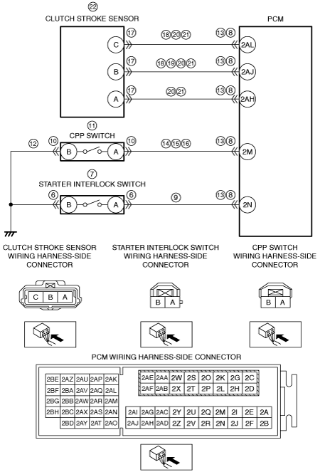
Refer to the wiring diagram and verify whether or not there is a common connector between starter interlock switch terminal A and PCM terminal 2N.
If there is a common connector:
• Determine the malfunctioning part by inspecting the common connector and the terminal for corrosion, damage, or pin disconnection, and the common wiring harness for a short to ground.
• Repair or replace the malfunctioning part.
If there is no common connector:
• Repair or replace the wiring harness which has a short to ground.
Go to Step 23.
|
|
No
|
Go to the next step.
|
|
10
|
INSPECT CPP SWITCH CONNECTOR CONDITION
• Switch the ignition off.
• Disconnect the CPP switch connector.
• Inspect for poor connection (such as damaged/pulled-out pins, corrosion).
• Is there any malfunction?
|
Yes
|
Repair or replace the connector and/or terminals, then go to Step 23.
|
|
No
|
Go to the next step.
|
|
11
|
INSPECT CPP SWITCH
• Inspect the CPP switch.
• Is there any malfunction?
|
Yes
|
Replace the CPP switch, then go to Step 23.
|
|
No
|
Go to the next step.
|
|
12
|
INSPECT CPP SWITCH GROUND CIRCUIT FOR OPEN CIRCUIT
• Verify that the CPP switch connector is disconnected.
• Inspect for continuity between CPP switch terminal B (wiring harness-side) and body ground.
• Is there continuity?
|
Yes
|
Go to the next step.
|
|
No
|
Refer to the wiring diagram and verify whether or not there is a common connector between CPP switch terminal B and body ground.
If there is a common connector:
• Determine the malfunctioning part by inspecting the common connector and the terminal for corrosion, damage, or pin disconnection, and the common wiring harness for an open circuit.
• Repair or replace the malfunctioning part.
If there is no common connector:
• Inspect for the following:
-
― Open circuit between CPP switch and body ground
― Loose or lifting ground point
-
• Repair or replace the malfunctioning part.
Go to Step 23.
|
|
13
|
INSPECT PCM CONNECTOR CONDITION
• Disconnect the PCM connector.
• Inspect for poor connection (such as damaged/pulled-out pins, corrosion).
• Is there any malfunction?
|
Yes
|
Repair or replace the connector and/or terminals, then go to Step 23.
|
|
No
|
Go to the next step.
|
|
14
|
INSPECT CPP SWITCH SIGNAL CIRCUIT FOR SHORT TO GROUND
• Verify that the CPP switch and PCM connectors are disconnected.
• Inspect for continuity between CPP switch terminal A (wiring harness-side) and body ground.
• Is there continuity?
|
Yes
|
Refer to the wiring diagram and verify whether or not there is a common connector between CPP switch terminal A and PCM terminal 2M.
If there is a common connector:
• Determine the malfunctioning part by inspecting the common connector and the terminal for corrosion, damage, or pin disconnection, and the common wiring harness for a short to ground.
• Repair or replace the malfunctioning part.
If there is no common connector:
• Repair or replace the wiring harness which has a short to ground.
Go to Step 23.
|
|
No
|
Go to the next step.
|
|
15
|
INSPECT CPP SWITCH SIGNAL CIRCUIT FOR SHORT TO POWER SUPPLY
• Verify that the CPP switch and PCM connectors are disconnected.
• Switch the ignition ON (engine off).
-
Note
-
• Another DTC may be stored by the PCM detecting an open circuit.
• Measure the voltage at the CPP switch terminal A (wiring harness-side).
• Is the voltage 0 V?
|
Yes
|
Go to the next step.
|
|
No
|
Refer to the wiring diagram and verify whether or not there is a common connector between CPP switch terminal A and PCM terminal 2M.
If there is a common connector:
• Determine the malfunctioning part by inspecting the common connector and the terminal for corrosion, damage, or pin disconnection, and the common wiring harness for a short to power supply.
• Repair or replace the malfunctioning part.
If there is no common connector:
• Repair or replace the wiring harness which has a short to power supply.
Go to Step 23.
|
|
16
|
INSPECT CPP SWITCH SIGNAL CIRCUIT FOR OPEN CIRCUIT
• Verify that the CPP switch and PCM connectors are disconnected.
• Switch the ignition off.
• Inspect for continuity between CPP switch terminal A (wiring harness-side) and PCM terminal 2M (wiring harness-side).
• Is there continuity?
|
Yes
|
Go to the next step.
|
|
No
|
Refer to the wiring diagram and verify whether or not there is a common connector between CPP switch terminal A and PCM terminal 2M.
If there is a common connector:
• Determine the malfunctioning part by inspecting the common connector and the terminal for corrosion, damage, or pin disconnection, and the common wiring harness for an open circuit.
• Repair or replace the malfunctioning part.
If there is no common connector:
• Repair or replace the wiring harness which has an open circuit.
Go to Step 23.
|
|
17
|
INSPECT CLUTCH STROKE SENSOR CONNECTOR CONDITION
• Disconnect the clutch stroke sensor connector.
• Inspect for poor connection (such as damaged/pulled-out pins, corrosion).
• Is there any malfunction?
|
Yes
|
Repair or replace the connector and/or terminals, then go to Step 23.
|
|
No
|
Go to the next step.
|
|
18
|
INSPECT CLUTCH STROKE SENSOR CIRCUIT FOR SHORT TO GROUND
• Verify that the clutch stroke sensor and PCM connectors are disconnected.
• Inspect for continuity between the following terminals (wiring harness-side) and body ground:
-
― Clutch stroke sensor terminal C
― Clutch stroke sensor terminal B
• Is there continuity?
|
Yes
|
Refer to the wiring diagram and verify whether or not there is a common connector between the following terminals:
• Clutch stroke sensor terminal C—PCM terminal 2AL
• Clutch stroke sensor terminal B—PCM terminal 2AJ
If there is a common connector:
• Determine the malfunctioning part by inspecting the common connector and the terminal for corrosion, damage, or pin disconnection, and the common wiring harness for a short to ground.
• Repair or replace the malfunctioning part.
If there is no common connector:
• Repair or replace the wiring harness which has a short to ground.
Go to Step 23.
|
|
No
|
Go to the next step.
|
|
19
|
INSPECT CLUTCH STROKE SENSOR SIGNAL CIRCUIT FOR SHORT TO POWER SUPPLY
• Verify that the clutch stroke sensor and PCM connectors are disconnected.
• Switch the ignition ON (engine off).
-
Note
-
• Another DTC may be stored by the PCM detecting an open circuit.
• Measure the voltage at the clutch stroke sensor terminal B (wiring harness-side).
• Is the voltage 0 V?
|
Yes
|
Go to the next step.
|
|
No
|
Refer to the wiring diagram and verify whether or not there is a common connector between clutch stroke sensor terminal B and PCM terminal 2AJ.
If there is a common connector:
• Determine the malfunctioning part by inspecting the common connector and the terminal for corrosion, damage, or pin disconnection, and the common wiring harness for a short to power supply.
• Repair or replace the malfunctioning part.
If there is no common connector:
• Repair or replace the wiring harness which has a short to power supply.
Go to Step 23.
|
|
20
|
INSPECT CLUTCH STROKE SENSOR CIRCUIT FOR SHORT TO EACH OTHER
• Verify that the clutch stroke sensor and PCM connectors are disconnected.
• Switch the ignition off.
• Inspect for continuity between clutch stroke sensor terminals C, B and A (wiring harness-side).
• Is there continuity?
|
Yes
|
Refer to the wiring diagram and verify whether or not there is a common connector between the following terminals:
• Clutch stroke sensor terminal C—PCM terminal 2AL
• Clutch stroke sensor terminal B—PCM terminal 2AJ
• Clutch stroke sensor terminal A—PCM terminal 2AH
If there is a common connector:
• Determine the malfunctioning part by inspecting the common connector and the terminal for corrosion, damage, or pin disconnection, and the common wiring harness for a short to each other.
• Repair or replace the malfunctioning part.
If there is no common connector:
• Repair or replace the wiring harness which has a short to each other.
Go to Step 23.
|
|
No
|
Go to the next step.
|
|
21
|
INSPECT CLUTCH STROKE SENSOR CIRCUIT FOR OPEN CIRCUIT
• Verify that the clutch stroke sensor and PCM connectors are disconnected.
• Inspect for continuity between the following terminals (wiring harness-side):
-
― Clutch stroke sensor terminal C—PCM terminal 2AL
― Clutch stroke sensor terminal B—PCM terminal 2AJ
― Clutch stroke sensor terminal A—PCM terminal 2AH
• Is there continuity?
|
Yes
|
Go to the next step.
|
|
No
|
Refer to the wiring diagram and verify whether or not there is a common connector between the following terminals:
• Clutch stroke sensor terminal C—PCM terminal 2AL
• Clutch stroke sensor terminal B—PCM terminal 2AJ
• Clutch stroke sensor terminal A—PCM terminal 2AH
If there is a common connector:
• Determine the malfunctioning part by inspecting the common connector and the terminal for corrosion, damage, or pin disconnection, and the common wiring harness for an open circuit.
• Repair or replace the malfunctioning part.
If there is no common connector:
• Repair or replace the wiring harness which has an open circuit.
Go to Step 23.
|
|
22
|
INSPECT CLUTCH STROKE SENSOR
• Inspect the clutch stroke sensor.
• Is there any malfunction?
|
Yes
|
Replace the clutch master cylinder, then go to the next step.
|
|
No
|
Repeat Step 5.
|
|
23
|
VERIFY DTC TROUBLESHOOTING COMPLETED
• Always reconnect all disconnected connectors.
• Clear the DTC from the PCM memory using the M-MDS.
• Depress and release the clutch pedal.
• Perform the DTC Reading Procedure.
• Is the same DTC present?
|
Yes
|
Repeat the inspection from Step 1.
• If the malfunction recurs, replace the PCM.
Go to the next step.
|
|
No
|
Go to the next step.
|
|
24
|
VERIFY AFTER REPAIR PROCEDURE
• Perform the “AFTER REPAIR PROCEDURE”.
• Are any DTCs present?
|
Yes
|
Go to the applicable DTC inspection.
|
|
No
|
DTC troubleshooting completed.
|