am6zzw00014437
|
DTC P0301:00, P0302:00, P0303:00, P0304:00 [SKYACTIV-D 2.2]
id0102s4703300
|
DTC P0301:00 |
Cylinder No.1 misfire detected |
|---|---|
|
DTC P0302:00 |
Cylinder No.2 misfire detected |
|
DTC P0303:00 |
Cylinder No.3 misfire detected |
|
DTC P0304:00 |
Cylinder No.4 misfire detected |
|
DETECTION CONDITION
|
• The misfire rate of specific cylinders for the crankshaft speed exceeds the specification for a continuous 16 s when the following conditions are met:
MONITORING CONDITIONS
Diagnostic support note
• This is an intermittent monitor (misfire).
• The check engine light illuminates if the PCM detects the above malfunction condition in two consecutive drive cycles or in one drive cycle while the DTC for the same malfunction has been stored in the PCM.
• PENDING CODE is available if the PCM detects the above malfunction condition during first drive cycle.
• FREEZE FRAME DATA/Snapshot data is available.
• DTC is stored in the PCM memory.
|
|
FAIL-SAFE FUNCTION
|
• Restrict the shifting of the automatic transaxle.
|
|
POSSIBLE CAUSE
|
• Fuel shortage in fuel tank
• Erratic signal to PCM
• CMP sensor malfunction
• Air suction or restriction in intake-air system (between MAF sensor and intake manifold)
• MAF sensor malfunction
• Turbocharger malfunction (turbine wheel and/or compressor wheel damaged, stuck)
• CKP sensor malfunction
• Fuel injector malfunction
• Fuel system malfunction
• Engine malfunction
• Poor fuel quality
• PCM malfunction
|
|
SYSTEM WIRING DIAGRAM
|
Not applicable
|
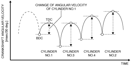
Function Explanation (DTC Detection Outline)
am6zzw00014437
|
|
MONITORING PARAMETER |
DTC |
IMAGE OF MONITORING |
|
|---|---|---|---|
|
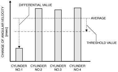
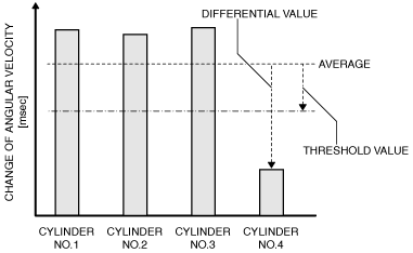
Change of crankshaft angular velocity during 1 injection
|
Cylinder No.1
|
P0301:00
|
 |
|
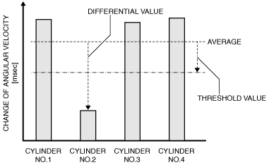
Cylinder No.2
|
P0302:00
|
 |
|
|
Change of crankshaft angular velocity during 1 injection
|
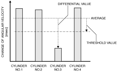
Cylinder No.3
|
P0303:00
|
 |
|
Cylinder No.4
|
P0304:00
|
 |
|
|
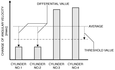
Multiple misfire
Example: If misfire occurs in cylinder No. 1 and cylinder No. 2
|
P0301:00
P0302:00
|
 |
|
Diagnostic Procedure
|
STEP |
INSPECTION |
ACTION |
|
|---|---|---|---|
|
1
|
RECORD FREEZE FRAME DATA/SNAPSHOT DATA AND DIAGNOSTIC MONITORING TEST RESULTS TO UTILIZE WITH REPEATABILITY VERIFICATION
• Record the FREEZE FRAME DATA/snapshot data and DIAGNOSTIC MONITORING TEST RESULTS (misfire related) on the repair order.
|
—
|
Go to the next step.
|
|
2
|
VERIFY RELATED SERVICE INFORMATION AVAILABILITY
• Verify related Service Information availability.
• Is any related Service Information available?
|
Yes
|
Perform repair or diagnosis according to the available Service Information.
• If the vehicle is not repaired, go to the next step.
|
|
No
|
Go to the next step.
|
||
|
3
|
VERIFY RELATED PENDING CODE AND/OR DTC
• Switch the ignition off, then ON (engine off).
• Perform the Pending Trouble Code Access Procedure and DTC Reading Procedure.
• Is the PENDING CODE/DTC P115A:00, P0313:00 or P115B:00 also present?
|
Yes
|
Go to the applicable PENDING CODE or DTC inspection.
|
|
No
|
Go to the next step.
|
||
|
4
|
VERIFY CURRENT INPUT SIGNAL STATUS (KEY TO ON/IDLE)
• Start the engine.
• Access the following PIDs using the M-MDS:
• Is there any signal that is far out of specification when the ignition is switched to ON and the engine idles?
|
Yes
|
Inspect the suspected sensor and related wiring harness.
Repair or replace the malfunctioning part according to the inspection results, then go to Step 17.
|
|
No
|
Go to the next step.
|
||
|
5
|
VERIFY CURRENT INPUT SIGNAL STATUS UNDER FREEZE FRAME DATA CONDITION
• Access the same PIDs as in Step 4 while simulating under the FREEZE FRAME DATA conditions.
• Is there any signal which causes drastic changes?
|
Yes
|
Inspect the suspected sensor and related wiring harness.
Repair or replace the malfunctioning part according to the inspection results, then go to Step 17.
|
|
No
|
Go to the next step.
|
||
|
6
|
INSPECT CMP SENSOR
• Inspect the CMP sensor.
• Is there any malfunction?
|
Yes
|
Replace the CMP sensor, then go to Step 17.
|
|
No
|
Go to the next step.
|
||
|
7
|
VERIFY CURRENT INPUT SIGNAL STATUS OF MAF SENSOR
• Start the engine.
• Access the MAF PID using the M-MDS.
• Verify that the MAF PID value changes quickly while increasing (racing) the engine rpm.
• Is the MAF PID value normal?
|
Yes
|
Go to Step 11.
|
|
No
|
Go to the next step.
|
||
|
8
|
INSPECT INTAKE AIR SYSTEM FOR EXCESSIVE AIR SUCTION
• Visually inspect for loose, cracked or damaged hoses on intake air system.
• Is there any malfunction?
|
Yes
|
Repair or replace the malfunctioning part according to the inspection results, then go to Step 17.
|
|
No
|
Go to the next step.
|
||
|
9
|
INSPECT FOR RESTRICTION OR CLOGGED IN INTAKE AIR SYSTEM
• Verify if there is restriction or clogged into the intake air system (such as between MAF sensor and intake manifold).
• Is there any malfunction?
|
Yes
|
Repair or replace the malfunctioning part according to the inspection results, then go to Step 17.
|
|
No
|
Go to the next step.
|
||
|
10
|
INSPECT TURBOCHARGER
• Inspect the turbocharger.
• Is there any malfunction?
|
Yes
|
Replace the turbocharger, then go to Step 17.
|
|
No
|
Replace the MAF sensor/IAT sensor No.1, then go to Step 17.
|
||
|
11
|
INSPECT CKP SENSOR
• Inspect the CKP sensor.
• Is there any malfunction?
|
Yes
|
Replace the CKP sensor, then go to Step 17.
|
|
No
|
Go to the next step.
|
||
|
12
|
INSPECT FUEL INJECTOR OPERATION
• Perform the Fuel Injector Operation Inspection.
• Is there any malfunction?
|
Yes
|
Repair or replace the malfunctioning part according to the inspection results, then go to Step 17.
|
|
No
|
Go to the next step.
|
||
|
13
|
INSPECT FOR LEAKAGE OR CLOGGED IN FUEL LINE
• For the cylinder which outputs a DTC, inspect the following fuel line for fuel leakage or clogging.
• Is there any malfunction?
|
Yes
|
Repair or replace the malfunctioning part according to the inspection results, then go to Step 17.
|
|
No
|
Go to the next step.
|
||
|
14
|
INSPECT ENGINE COMPRESSION
• Inspect the engine compression.
• Are compression pressures within specification?
Specification:
• Compression
|
Yes
|
Go to the next step.
|
|
No
|
Repair or replace the malfunctioning part according to the inspection results, then go to Step 17.
|
||
|
15
|
INSPECT SEALING OF ENGINE COOLANT PASSAGE
• Perform the “ENGINE COOLANT LEAKAGE INSPECTION”.
• Does the radiator cap tester needle drop even though there is no engine coolant leakage from the radiator or the hoses?
|
Yes
|
Engine coolant leakage from the engine (between the combustion chamber and the engine coolant passage) may have occurred.
• Verify the conditions of the gasket and the cylinder head.
|
|
No
|
Go to the next step.
|
||
|
16
|
INSPECT FOR MALFUNCTION DUE TO POOR FUEL
• Replace the fuel.
• Clear the DTC from the PCM memory using the M-MDS.
• Access the ECT PID using the M-MDS.
• Start the engine and idle it.
• Wait until the ECT PID value is above 60 °C {140 °F}.
• Wait for 1 min (idle).
• Perform the Pending Trouble Code Access Procedure.
• Is the PENDING CODE for this DTC present?
|
Yes
|
Remove the accumulated matter in the cylinder head using the following procedure, then go to the next step.
• Carbon remover
• Overhauling
|
|
No
|
Advise the customer as to the change in the fuel used.
Go to Step 18.
|
||
|
17
|
VERIFY DTC TROUBLESHOOTING COMPLETED
• Always reconnect all disconnected connectors.
• Clear the DTC from the PCM memory using the M-MDS.
• Access the ECT PID using the M-MDS.
• Start the engine and idle it.
• Wait until the ECT PID value is above 60 °C {140 °F}.
• Wait for 1 min (idle).
• Perform the Pending Trouble Code Access Procedure.
• Is the PENDING CODE for this DTC present?
|
Yes
|
Repeat the inspection from Step 1.
• If the malfunction recurs, replace the PCM.
Go to the next step.
|
|
No
|
Go to the next step.
|
||
|
18
|
VERIFY AFTER REPAIR PROCEDURE
• Perform the “AFTER REPAIR PROCEDURE”.
• Are any DTCs present?
|
Yes
|
Go to the applicable DTC inspection.
(See DTC TABLE [SKYACTIV-D 2.2].)
|
|
No
|
DTC troubleshooting completed.
|
||