 |
am3zzw00013778
TURBOCHARGER REMOVAL/INSTALLATION [SKYACTIV-D 2.2]
id0113z7705800
Operation After Replacing or Removal/Installation Turbocharger
1. If the turbocharger is replaced or removed/installed, perform the following procedure.
|
STEP |
ACTION |
PAGE/CONDITION |
|---|---|---|
|
1
|
Perform turbocharger initialization procedure.
|
|
|
2
|
Wait for 20 s.
|
—
|
|
3
|
Perform KOEO self-test procedure.
|
|
|
4
|
Perform KOER self-test procedure.
|
Turbocharger Removal/Installation
1. Disconnect the negative battery cable. (See NEGATIVE BATTERY CABLE DISCONNECTION/CONNECTION [SKYACTIV-D 2.2].)
2. Remove the engine cover. (See ENGINE COVER REMOVAL/INSTALLATION [SKYACTIV-D 2.2].)
3. Drain the engine coolant. (See ENGINE COOLANT REPLACEMENT [SKYACTIV-D 2.2].)
4. Remove the air cleaner. (See INTAKE-AIR SYSTEM REMOVAL/INSTALLATION [SKYACTIV-D 2.2].)
5. Remove the battery and the battery tray. (See BATTERY REMOVAL/INSTALLATION [SKYACTIV-D 2.2].)
6. Remove the following parts as a single unit: (See INTAKE-AIR SYSTEM REMOVAL/INSTALLATION [SKYACTIV-D 2.2].)
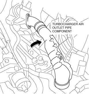
7. Set the turbocharger air outlet pipe component aside as a single unit as shown in the figure. (See INTAKE-AIR SYSTEM REMOVAL/INSTALLATION [SKYACTIV-D 2.2].)
am3zzw00013778
|
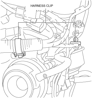
8. Remove the wiring harness clip shown in the figure.
ac5wzw00004706
|
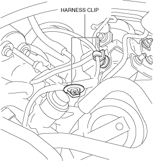
9. Disconnect the regulating valve position sensor connector.
10. Detach the wiring harness clips shown in the figure.
ac5wzw00004707
|
11. Remove the front crossmember. (See FRONT CROSSMEMBER REMOVAL/INSTALLATION [SKYACTIV-D 1.5, SKYACTIV-D 2.2].)
12. Remove the catalytic converter. (See EXHAUST SYSTEM REMOVAL/INSTALLATION [SKYACTIV-D 2.2].)
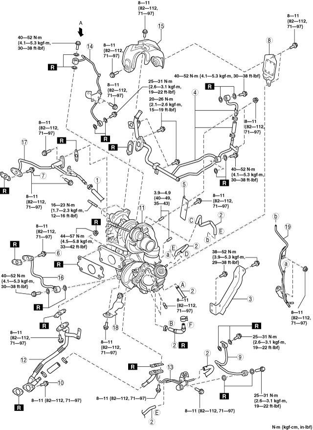
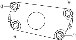
13. Remove in the order shown in the figure.
14. Install in the reverse order of removal.
15. Refill the engine coolant. (See ENGINE COOLANT REPLACEMENT [SKYACTIV-D 2.2].)
16. Perform the following procedure.
am3zzw00013779
|
|
1
|
Water hose
|
|
2
|
Vacuum hose
|
|
3
|
Turbocharger bracket
|
|
4
|
Water pipe No.1
|
|
5
|
Turbocharger insulator No.1
|
|
6
|
Water pipe No.2 installation bolt
|
|
7
|
Water pipe No.3 installation bolt
|
|
8
|
Turbocharger insulator No.2
|
|
9
|
Oil pipe No.1
|
|
10
|
Oil pipe No.2 installation bolt
|
|
11
|
Turbocharger
|
|
12
|
Oil pipe No.2
(See Oil pipe No.2 removal note.)
|
|
13
|
Oil pipe No.3
|
|
14
|
Oil pipe No.4
|
|
15
|
Turbocharger insulator No.3
|
|
16
|
Water pipe No.2
|
|
17
|
Water pipe No.3
|
|
18
|
Turbocharger insulator No.4
|
|
19
|
Vacuum pipe
|
Oil pipe No.2 removal note
1. Remove oil pipes No.2 and 3 as a single unit.
2. Remove oil pipe No.2.
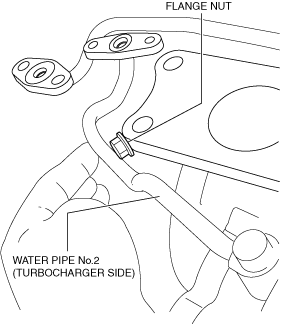
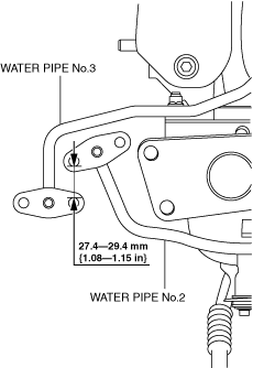
Water pipe No.2 installation note
1. Insert a flange nut (M10 (Approx. 9 mm {0.4 in}) between the position shown in the figure and tighten water pipe No.2 (turbocharger side).
am3zzw00016722
|
2. Measure the distance shown in the figure and verify that water pipe No.2 is installed correctly.
am3zzw00016723
|
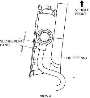
Oil pipe No.4 installation note
1. Secure oil pipe No.4 using a wrench so that it does not rotate.
am3zzw00016724
|
2. Tighten the oil pipe No.4.
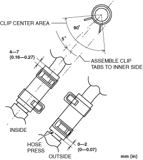
Oil pipe No.2 installation note
1. Install the oil pipe No.2 as shown in the figure.
am3zzw00013780
|
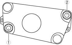
Turbocharger installation note
1. Install the turbocharger using the following procedure.
ac5wzw00005703
|
ac5wzw00005745
|
Vacuum hose installation note
1. Install the vacuum hose as shown in the figure.
am3zzw00013781
|