|
1
|
VERIFY RELATED SERVICE INFORMATION AVAILABILITY
• Verify related Service Information availability.
• Is any related Service Information available?
|
Yes
|
Perform repair or diagnosis according to the available Service Information.
• If the vehicle is not repaired, go to the next step.
|
|
No
|
Go to the next step.
|
|
2
|
VERIFY DTC FOR MODULE COMMUNICATION
• Switch the ignition off, then ON (engine off).
• Perform the DTC Reading Procedure.
• Are any other PENDING CODEs and/or DTCs present?
|
Yes
|
Go to the applicable PENDING CODE or DTC inspection.
|
|
No
|
Go to the next step.
|
|
3
|
CONFIRM FRONT BODY CONTROL MODULE (FBCM) DTC
• Perform the front body control module (FBCM) DTC inspection using the M-MDS.
• Are any DTCs present?
|
Yes
|
Go to the applicable DTC inspection.
|
|
No
|
Go to the next step.
|
|
4
|
CONFIRM SAS CONTROL MODULE DTC
• Perform the SAS control module DTC inspection using the M-MDS.
• Are any DTCs present?
|
Yes
|
Go to the applicable DTC inspection.
|
|
No
|
Go to the next step.
|
|
5
|
CONFIRM INSTRUMENT CLUSTER DTC
• Perform the instrument cluster DTC inspection using the M-MDS.
• Are any DTCs present?
|
Yes
|
Go to the applicable DTC inspection.
|
|
No
|
Go to the next step.
|
|
6
|
INSPECT SAS CONTROL MODULE CONNECTOR CONDITION
• Switch the ignition off.
• Disconnect the SAS control module connector.
• Inspect for poor connection (such as damaged/pulled-out pins, corrosion).
• Is there any malfunction?
|
Yes
|
Repair or replace the connector and/or terminals, then go to Step 8.
|
|
No
|
Go to the next step.
|
|
7
|
INSPECT PCM CONNECTOR CONDITION
• Disconnect the PCM connector.
• Inspect for poor connection (such as damaged/pulled-out pins, corrosion).
• Is there any malfunction?
|
Yes
|
Repair or replace the connector and/or terminals, then go to the next step.
|
|
No
|
CAN communication line can be considered the cause.
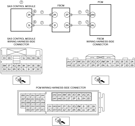
• Refer to the wiring diagram and verify whether or not there is a common connector between the following terminals:
-
― SAS control module terminal 3K—Front body control module (FBCM) terminal 2K
― SAS control module terminal 3L—Front body control module (FBCM) terminal 2I
― Front body control module (FBCM) terminal 2P—PCM terminal 2AK
― Front body control module (FBCM) terminal 2N—PCM terminal 2AL
If there is a common connector:
-
― Determine the malfunctioning part by inspecting the common connector and the terminal for corrosion, damage, or pin disconnection, and the common wiring harness for a malfunction.
― Repair or replace the malfunctioning part.
If there is no common connector:
-
― Repair or replace the wiring harness.
If the malfunction recurs, replace the SAS control module.
Go to the next step.
|
|
8
|
VERIFY DTC TROUBLESHOOTING COMPLETED
• Always reconnect all disconnected connectors.
• Clear the DTC from the PCM memory using the M-MDS.
• Perform the KOEO or KOER self test.
• Is the same DTC present?
|
Yes
|
Repeat the inspection from Step 1.
• If the malfunction recurs, replace the PCM.
Go to the next step.
|
|
No
|
Go to the next step.
|
|
9
|
VERIFY AFTER REPAIR PROCEDURE
• Perform the “AFTER REPAIR PROCEDURE”.
• Are any DTCs present?
|
Yes
|
Go to the applicable DTC inspection.
|
|
No
|
DTC troubleshooting completed.
|