 |
am3zzw00016395
FUEL TANK REMOVAL/INSTALLATION [MZR 1.6]
id0114f4801600
1. Level the vehicle.
2. Complete the “BEFORE SERVICE PRECAUTION”. (See BEFORE SERVICE PRECAUTION [MZR 1.6].)
3. Drain the fuel. (See FUEL DRAINING PROCEDURE [MZR 1.6].)
4. Remove the rear seat cushion. (See REAR SEAT CUSHION REMOVAL/INSTALLATION.)
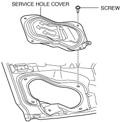
5. Remove the service hole cover.
am3zzw00016395
|
6. Disconnect the following parts:
7. Remove the floor under cover. (See FLOOR UNDER COVER REMOVAL/INSTALLATION.)
8. Disconnect the HO2S connector.
9. Remove the presilencer and HO2S as a single unit. (See EXHAUST SYSTEM REMOVAL/INSTALLATION [MZR 1.6].)
10. Remove in the order indicated in the table.
11. Install in the reverse order of removal.
12. Complete the “AFTER SERVICE PRECAUTION”. (See AFTER SERVICE PRECAUTION [MZR 1.6].)
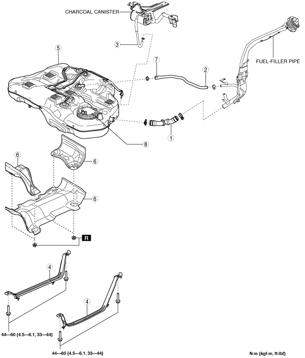
Fuel tank type A
am3uuw00012204
|
|
1
|
Joint hose
(See Joint Hose Installation Note.)
|
|
2
|
Breather hose (fuel-filler pipe side)
|
|
3
|
Evaporative hose
|
|
4
|
Fuel tank strap
|
|
5
|
Fuel tank
(See Fuel Tank Removal Note.)
|
|
6
|
Fuel tank insulator
|
|
7
|
Breather hose (fuel tank side)
|
|
8
|
Fuel pump unit
|
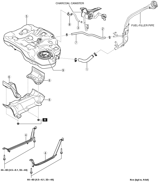
Fuel tank type B
am3zzw00016314
|
|
1
|
Joint hose
(See Joint Hose Installation Note.)
|
|
2
|
Breather hose (fuel-filler pipe side)
|
|
3
|
Evaporative hose (check valve side)
|
|
4
|
Fuel tank strap
|
|
5
|
Fuel tank
(See Fuel Tank Removal Note.)
|
|
6
|
Fuel tank insulator
|
|
7
|
Breather hose (fuel tank side)
|
|
8
|
Quick release connector
|
|
9
|
Fuel pump unit
|
Fuel Tank Removal Note
1. Disconnect the breather hose from the fuel-filler pipe side.
2. Disconnect the evaporative hose (between charcoal canister and check valve) from the check valve side.
3. Remove the following parts as single unit:
4. Remove the fuel tank.
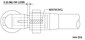
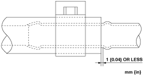
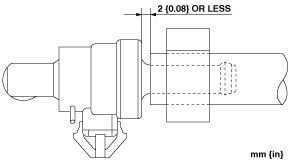
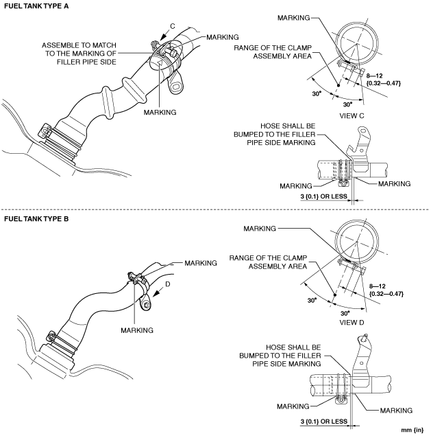
Breather Hose Installation Note
1. Install the breather hose as shown in the figure.
Fuel tank side
am3zzw00016396
|
Fuel-filler pipe side
am3zzw00016397
|
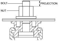
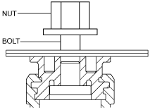
Fuel Tank Insulator Installation Note
am3zzw00016412
|
1. Temporarily tighten the fuel tank insulator installation nuts until the upper surface of the nuts are flush with the bolt ends.
am3zzw00016413
|
2. Tighten the fuel tank insulator installation nuts.
Evaporative Hose Installation Note
1. Install the evaporative hose as shown in the figure.
am3uuw00012205
|
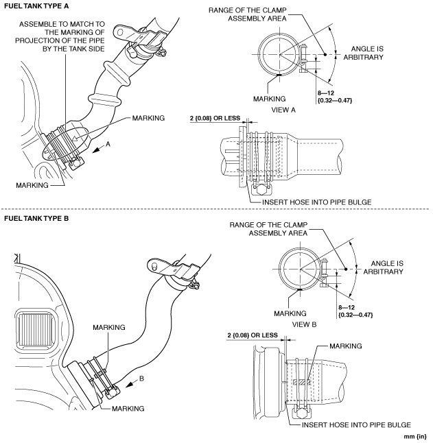
Joint Hose Installation Note
1. Install the joint hose as shown in the figure.
Fuel tank side
am3zzw00016315
|
Fuel-filler pipe side
am3zzw00016316
|