 |
ac3wzw00001391
LOWER CASE REMOVAL/INSTALLATION [SKYACTIV-D 1.5]
id0114q2266300
1. Disconnect the negative battery cable. (See NEGATIVE BATTERY CABLE DISCONNECTION/CONNECTION [SKYACTIV-D 1.5].)
2. Remove the engine cover. (See ENGINE COVER REMOVAL/INSTALLATION [SKYACTIV-D 1.5].)
3. Complete the “BEFORE SERVICE PRECAUTION”. (See BEFORE SERVICE PRECAUTION [SKYACTIV-D 1.5].)
4. Remove the air inlet pipe. (See INTAKE-AIR SYSTEM REMOVAL/INSTALLATION [SKYACTIV-D 1.5].)
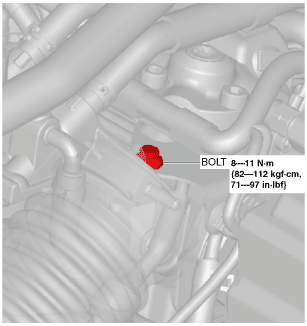
5. Remove the vacuum pipe bolt shown in the figure.
ac3wzw00001391
|
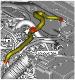
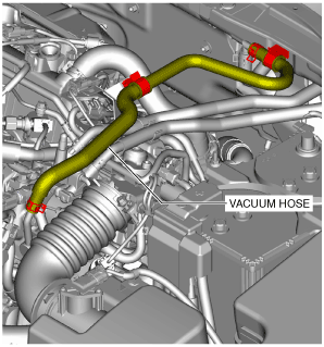
6. Remove the vacuum hose shown in the figure.
L.H.D.
am3zzw00017409
|
R.H.D.
am3zzw00017410
|
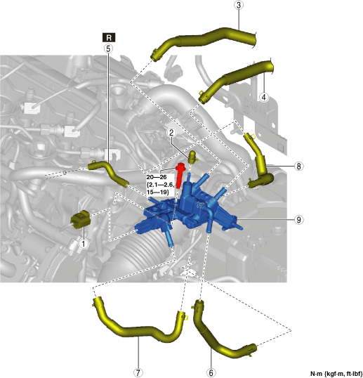
7. Remove in the order shown in the figure.
8. Install in the reverse order of removal.
9. Complete the “AFTER SERVICE PRECAUTION”. (See AFTER SERVICE PRECAUTION [SKYACTIV-D 1.5].)
am3zzw00019945
|
|
1
|
Fuel temperature sensor connector
|
|
2
|
Blind cap
(See Blind Cap Installation Note.)
|
|
3
|
Fuel main hose No.1
|
|
4
|
Fuel return hose No.1
|
|
5
|
Fuel return hose No.2
|
|
6
|
Fuel main hose No.2
|
|
7
|
Fuel return hose No.3
|
|
8
|
Fuel return hose No.4
|
|
9
|
Lower case
(See Lower Case Removal Note.)
(See Lower Case Installation Note.)
|
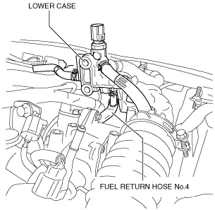
Fuel Return Hose No.4 Removal Note
1. Remove the lower case bolts and turn the lower case upside down.
am2zzw00012079
|
2. Disconnect fuel return hose No.4 from the lower case.
Lower Case Removal Note
1. Remove the following parts as a single unit:
am2zzw00012080
|
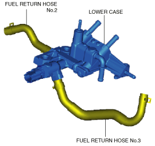
2. Remove fuel return hose No.2 and fuel return hose No.3 from the lower case.
Lower Case Installation Note
1. Install the following parts as a single unit:
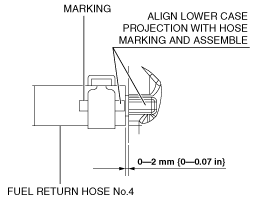
Fuel Return Hose No.4 Installation Note
1. Install fuel return hose No.4 as shown in the figure.
ac3wzw00001392
|
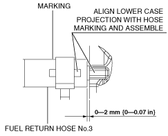
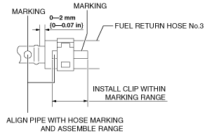
Fuel Return Hose No.3 Installation Note
1. Install fuel return hose No.3 as shown in the figure.
Lower case side
ac3wzw00001393
|
Supply pump side
ac3wzw00001394
|
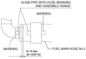
Fuel Main Hose No.2 Installation Note
1. Install fuel main hose No.2 as shown in the figure.
ac3wzw00001395
|
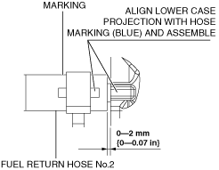
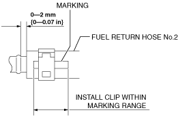
Fuel Return Hose No.2 Installation Note
1. Install fuel return hose No.2 as shown in the figure.
Lower case side
am2zzw00013053
|
Common rail side
ac3wzw00001397
|
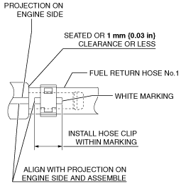
Fuel Return Hose No.1 Installation Note
1. Install fuel return hose No.1 as shown in the figure.
am2zzw00012088
|
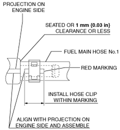
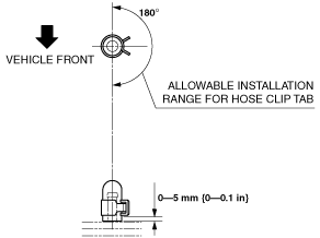
Fuel Main Hose No.1 Installation Note
1. Install fuel main hose No.1 as shown in the figure.
am2zzw00012089
|
Blind Cap Installation Note
1. Install blind cap as shown in the figure.
am2zzw00012081
|