 |
am3zzw00017424
FUEL INJECTOR REMOVAL/INSTALLATION [SKYACTIV-D 1.5]
id0114q2800600
Operation After Replacing Fuel Injector
1. If the fuel injector is replaced, perform the following procedure.
|
STEP |
ACTION |
PAGE/CONDITION |
|---|---|---|
|
1
|
Perform fuel injector code programming.
|
|
|
2
|
Perform fuel injector data reset procedure.
|
|
|
3
|
Clear the DTCs.
|
|
|
4
|
Switch the ignition off.
|
—
|
|
5
|
Wait for 20 s or more.
|
—
|
|
6
|
Perform KOEO self-test procedure.
|
|
|
7
|
Perform KOER self-test procedure.
|
|
|
8
|
Perform fuel injector injection amount correction.
|
|
|
9
|
Clear the DTCs.
|
Fuel injector Removal/Installation
1. Disconnect the negative battery cable. (See NEGATIVE BATTERY CABLE DISCONNECTION/CONNECTION [SKYACTIV-D 1.5].)
2. Remove the engine cover. (See ENGINE COVER REMOVAL/INSTALLATION [SKYACTIV-D 1.5].)
3. Complete the “BEFORE SERVICE PRECAUTION”. (See BEFORE SERVICE PRECAUTION [SKYACTIV-D 1.5].)
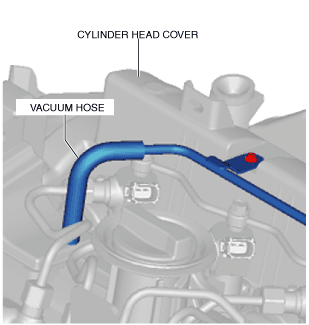
4. Disconnect the vacuum hose connected to the cylinder head cover.
am3zzw00017424
|
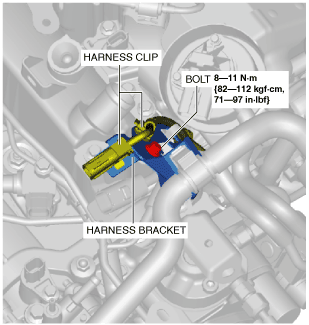
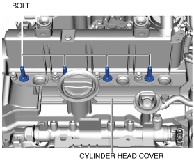
5. Remove the wiring harness clips and bolt shown in the figure and set the wiring harness bracket aside so that it does not interfere with the servicing.
ac3wzw00001404
|
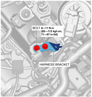
6. Remove the bolts, and remove the wiring harness bracket.
ac3wzw00001405
|
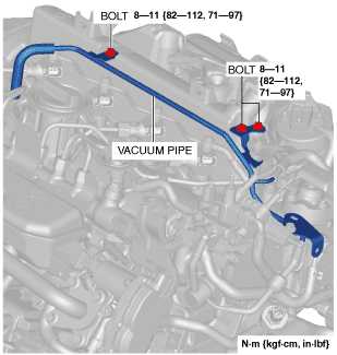
7. Remove the vacuum pipe installation bolt and set the vacuum pipe aside so that it does not interfere with the servicing.
am3zzw00017425
|
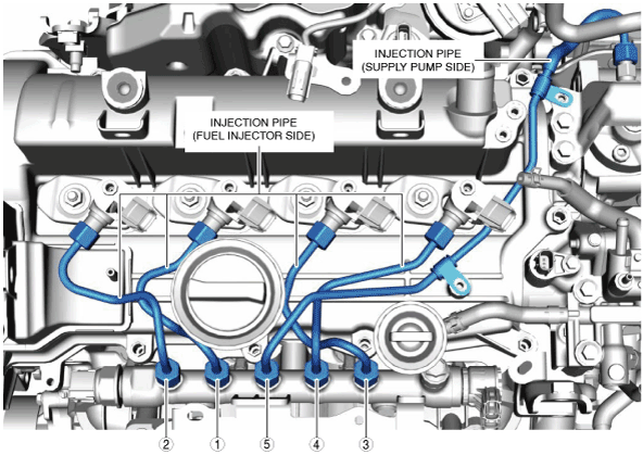
8. Remove the injection pipe (fuel injector side). (See INJECTION PIPE REMOVAL/INSTALLATION [SKYACTIV-D 1.5].)
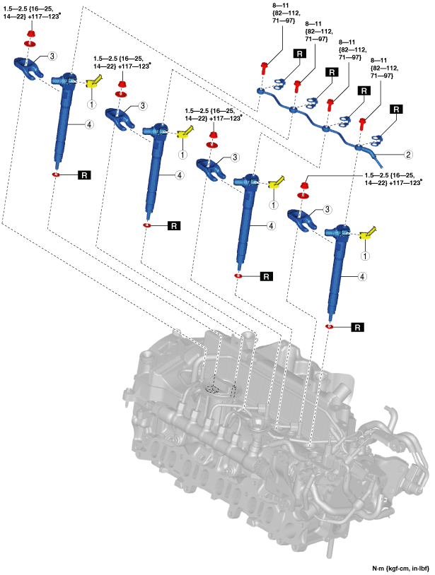
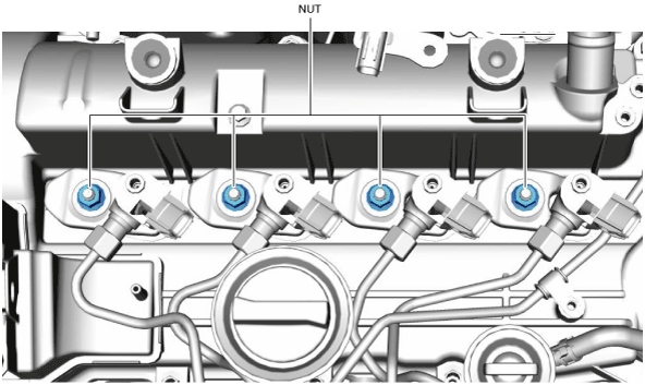
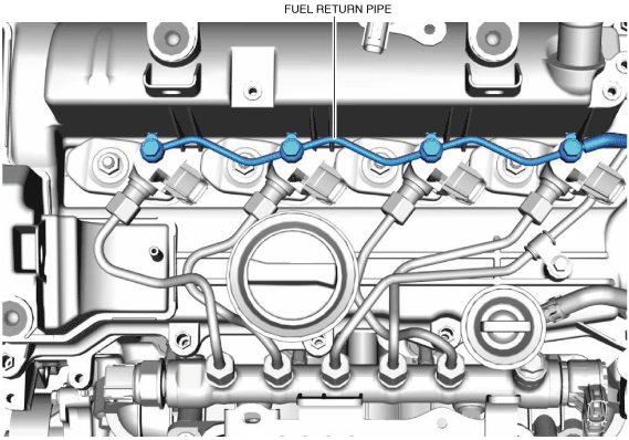
9. Remove in the order shown in the figure.
10. Install in the reverse order of removal.
11. Complete the “AFTER SERVICE PRECAUTION”. (See AFTER SERVICE PRECAUTION [SKYACTIV-D 1.5].)
am2zzw00012105
|
|
1
|
Fuel injector connector
|
|
2
|
Fuel return pipe
|
|
3
|
Fuel injector bracket
|
|
4
|
Fuel injector
|
Fuel injector installation note
1. Remove the injection pipe (supply pump side). (See INJECTION PIPE REMOVAL/INSTALLATION [SKYACTIV-D 1.5].)
2. Loosen the common rail.
3. Tighten the bolts shown in the figure to the specified torque.
ac3wzw00002429
|
am6xuw00012307
|
|
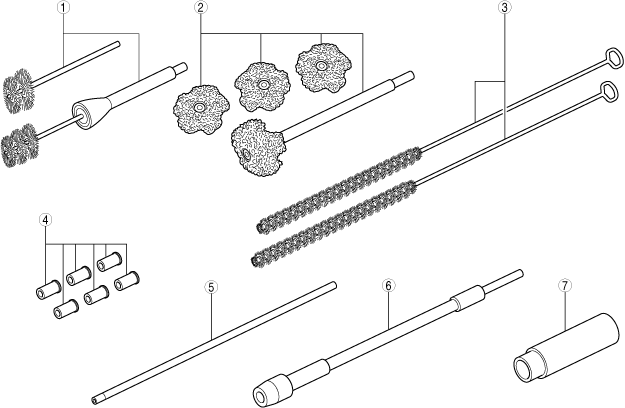
1
|
Round wire brush
|
|
2
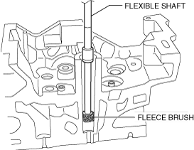
|
Fleece brush
|
|
3
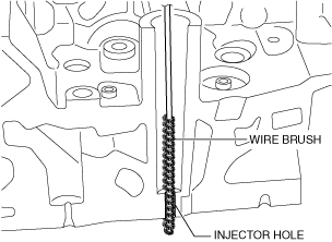
|
Wire brush
|
|
4
|
Blanking plug
|
|
5
|
Extension bar
|
|
6
|
Flexible shaft
|
|
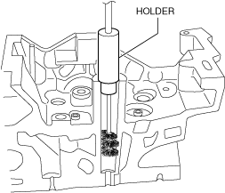
7
|
Holder
|
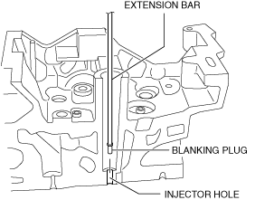
4. Install the blanking plug to the end of the extension bar.
5. Insert the blanking plug into the injector hole, rotate the extension bar counterclockwise, and then block the injector hole using the blanking plug.
am6xuw00012308
|
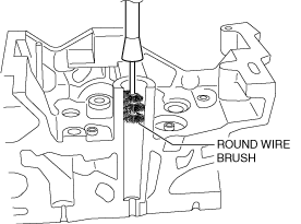
6. Install the round wire brush to the end of the flexible shaft.
am6xuw00012309
|
am6xuw00012310
|
7. Connect the flexible shaft installed to the round wire brush to the drill, and clean the bore.
8. Clean the carbon that was cut off using an air gun.
9. Cut (reference: diameter approx. 23 mm) the fleece brush so that it reaches the bottom surface, and install it to the flexible shaft.
10. Connect the flexible shaft installed to the fleece brush to the drill, and clean the bottom surface.
am6xuw00012311
|
11. Clean the carbon that was cut off using an air gun.
12. Insert the extension bar and remove the blanking plug.
13. Clean the injector hole using a wire brush.
am6xuw00012312
|
14. Temporarily install the fuel injector and the fuel injector bracket.
15. Temporarily tighten the common rail installation nut.
16. Temporarily tighten both ends of the new injection pipe (fuel injector side) and injection pipe (supply pump side) in the order shown in the figure.
ac3wzw00002430
|
17. Tighten the fuel injector bracket installation nuts in two steps.
ac3wzw00002431
|
18. Tighten the injection pipe (supply pump side) bracket installation bolts.
ac3wzw00002432
|
19. Tighten both ends of the injection pipe (fuel injector side).
20. Tighten both ends of the injection pipe (supply pump side).
21. Tighten the common rail.
22. Tighten the fuel return pipe.
ac3wzw00002433
|