 |
am2zzw00012138
INJECTION PIPE REMOVAL/INSTALLATION [SKYACTIV-D 1.5]
id0114q2850200
1. Disconnect the negative battery cable. (See NEGATIVE BATTERY CABLE DISCONNECTION/CONNECTION [SKYACTIV-D 1.5].)
2. Remove the engine cover. (See ENGINE COVER REMOVAL/INSTALLATION [SKYACTIV-D 1.5].)
3. Complete the “BEFORE SERVICE PRECAUTION”. (See BEFORE SERVICE PRECAUTION [SKYACTIV-D 1.5].)
4. Remove the EGR pipe. (See EGR PIPE REMOVAL/INSTALLATION [SKYACTIV-D 1.5].)
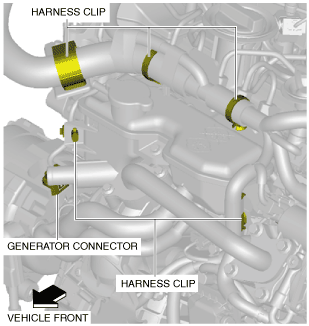
5. Remove the wiring harness clips and the generator connector shown in the figure.
am2zzw00012138
|
6. Set the water-cooled charge air cooler reserve tank aside so that it does not interfere with the servicing. (See WATER-COOLED CHARGE AIR COOLER RESERVE TANK REMOVAL/INSTALLATION [SKYACTIV-D 1.5].)
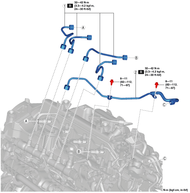
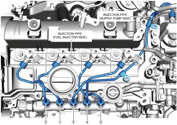
7. Remove in the order shown in the figure.
8. Install in the reverse order of removal.
9. Complete the “AFTER SERVICE PRECAUTION”. (See AFTER SERVICE PRECAUTION [SKYACTIV-D 1.5].)
am2zzw00012139
|
|
1
|
Injection pipe (fuel injector side)
|
|
2
|
Injection pipe (supply pump side)
|
Injection Pipe (Supply Pump Side) Removal Note
1. Remove the air inlet pipe. (See INTAKE-AIR SYSTEM REMOVAL/INSTALLATION [SKYACTIV-D 1.5].)
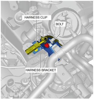
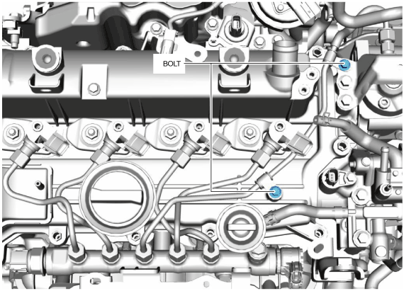
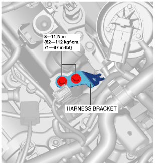
2. Remove the wiring harness clips and bolt shown in the figure and set the wiring harness bracket aside so that it does not interfere with the servicing.
am2zzw00012140
|
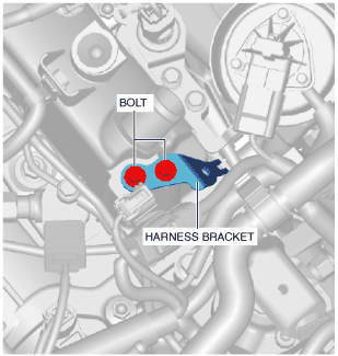
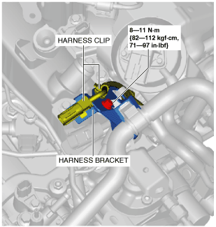
3. Remove the bolts, and remove the wiring harness bracket.
am2zzw00012141
|
4. Disconnect the fuel return hose shown in the figure.
am2zzw00012142
|
5. Remove the injection pipe (supply pump side).
Injection Pipe Installation Note
1. Remove the fuel injector bracket. (See FUEL INJECTOR REMOVAL/INSTALLATION [SKYACTIV-D 1.5].)
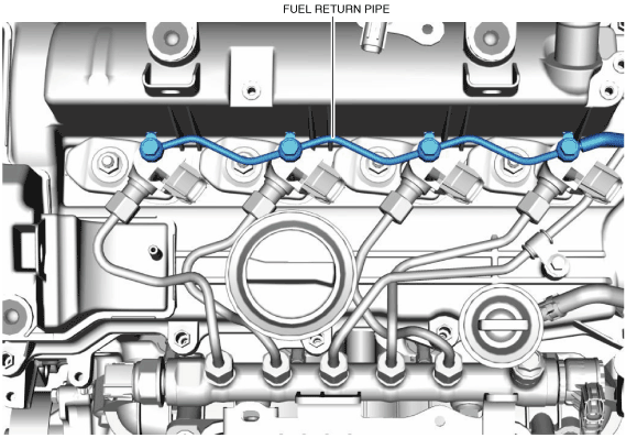
2. Remove the fuel return pipe. (See FUEL INJECTOR REMOVAL/INSTALLATION [SKYACTIV-D 1.5].)
3. Loosen the common rail.
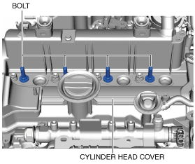
4. Tighten the bolts shown in the figure to the specified torque.
ac3wzw00002439
|
5. Temporarily install the fuel injector bracket.
6. Temporarily tighten the common rail installation nut.
7. Temporarily tighten both ends of the new injection pipe (fuel injector side) and injection pipe (supply pump side) in the order shown in the figure.
ac3wzw00002440
|
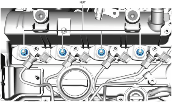
8. Tighten the fuel injector bracket installation nuts in two steps.
ac3wzw00002441
|
9. Tighten the injection pipe (supply pump side) bracket installation bolts.
ac3wzw00002442
|
10. Tighten both ends of the injection pipe (fuel injector side).
11. Tighten both ends of the injection pipe (supply pump side).
12. Tighten the common rail.
13. Tighten the fuel return pipe.
ac3wzw00002443
|
14. Connect the fuel return hose as shown in the figure.
am2zzw00012142
|
15. Install the harness bracket as shown in the figure.
ac3wzw00001439
|
16. Install the harness bracket as shown in the figure.
ac3wzw00001440
|
17. Install the air inlet pipe. (See INTAKE-AIR SYSTEM REMOVAL/INSTALLATION [SKYACTIV-D 1.5].)