|
am3zzw00017036
FUEL PUMP UNIT REMOVAL/INSTALLATION [SKYACTIV-G 1.5, SKYACTIV-G 2.0, SKYACTIV-G 2.5]
id0114zc800900
Fuel Pump Unit Type A
1. Complete the “BEFORE SERVICE PRECAUTION”. (See BEFORE SERVICE PRECAUTION [SKYACTIV-G 1.5, SKYACTIV-G 2.0, SKYACTIV-G 2.5].)
2. Using the following procedure:
3. Remove the rear seat cushion. (See REAR SEAT CUSHION REMOVAL/INSTALLATION.)
4. Remove the service hole cover.
am3zzw00017036
|
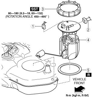
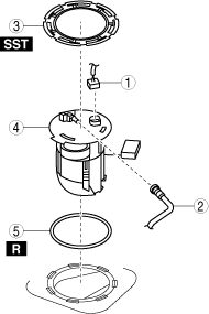
5. Remove in the order indicated in the table.
Packing part No. D350-*****
am3uuw00013912
|
|
1
|
Fuel pump unit connector
|
|
2
|
Quick release connector
|
|
3
|
Fuel pump cap
(See Fuel pump cap removal note.)
|
|
4
|
Fuel pump unit
|
|
5
|
Packing
(See Packing installation note.)
|
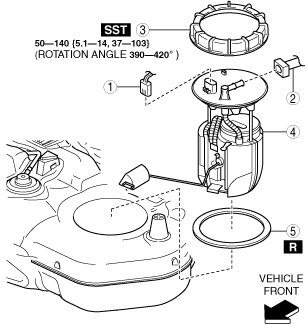
Except packing part No. D350-*****
am3zzw00034261
|
|
1
|
Fuel pump unit connector
|
|
2
|
Quick release connector
|
|
3
|
Fuel pump cap
(See Fuel pump cap removal note.)
|
|
4
|
Fuel pump unit
|
|
5
|
Packing
(See Packing installation note.)
|
6. Install in the reverse order of removal.
7. Complete the “AFTER SERVICE PRECAUTION”. (See AFTER SERVICE PRECAUTION [SKYACTIV-G 1.5, SKYACTIV-G 2.0, SKYACTIV-G 2.5].)
Fuel pump cap removal note
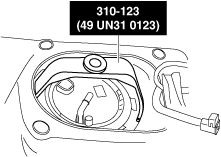
1. Remove the fuel pump cap using the SST.
am3zzw00017037
|
Packing installation note
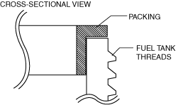
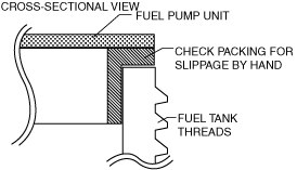
1. Install the packing so that it is adhered around the entire fuel tank opening.
ac3uuw00001480
|
Fuel pump unit installation note
1. After installing the fuel pump unit, verify by hand that the packing is installed correctly all the way around without any slippage.
ac3uuw00001482
|
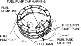
Fuel pump cap installation note (packing part No. D350-*****)
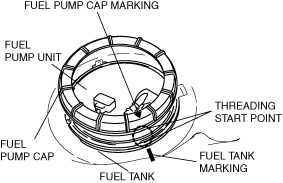
1. Mark the fuel pump cap and the fuel tank at the point where the threading of each part begins as shown in the figure.
am3zzw00017038
|
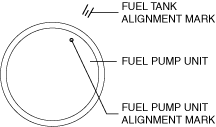
2. Align the fuel tank alignment mark with the fuel pump unit as shown in the figure.
am3zzw00017039
|
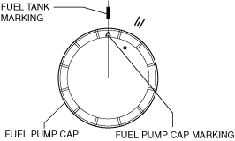
3. Align the fuel tank and fuel pump cap markings.
am3zzw00017040
|
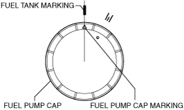
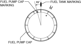
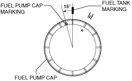
4. Rotate the fuel pump cap counterclockwise until the cap marking is approx. 15° away from the fuel tank marking as shown in the figure.
am3zzw00017041
|
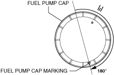
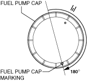
5. While keeping the fuel pump unit from rising up, tighten the fuel pump cap by hand 180 ° clockwise.
am3zzw00017042
|
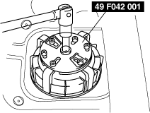
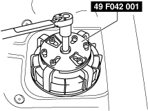
6. Set the SST as shown in the figure.
adejjw00015496
|
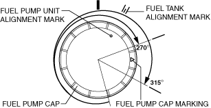
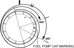
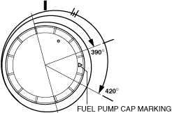
7. Using a torque wrench, tighten the fuel pump cap with both of the following specified rotation angle and specified torque met being careful not to shift the marks on the fuel pump unit and fuel tank.
am3zzw00017043
|
am3zzw00017044
|
Fuel pump cap installation note (except packing part No. D350-*****)
1. Mark the fuel pump cap and the fuel tank at the point where the threading of each part begins as shown in the figure.
am3uuw00011133
|
2. Align the fuel tank alignment mark with the fuel pump unit as shown in the figure.
am3uuw00011134
|
3. Align the fuel tank and fuel pump cap markings.
am3uuw00011135
|
4. Rotate the fuel pump cap counterclockwise until the cap marking is approx. 15° away from the fuel tank marking as shown in the figure.
am3uuw00011136
|
5. While keeping the fuel pump unit from rising up, tighten the fuel pump cap by hand 180 ° clockwise.
am3uuw00011137
|
6. Set the SST as shown in the figure.
adejjw00015496
|
7. Using a torque wrench, tighten the fuel pump cap with both of the following specified rotation angle and specified torque met being careful not to shift the marks on the fuel pump unit and fuel tank.
am3zzw00034262
|
am3zzw00034263
|
Fuel Pump Unit Type B
1. Complete the “BEFORE SERVICE PRECAUTION”. (See BEFORE SERVICE PRECAUTION [SKYACTIV-G 1.5, SKYACTIV-G 2.0, SKYACTIV-G 2.5].)
2. Using the following procedure:
3. Remove the rear seat cushion. (See REAR SEAT CUSHION REMOVAL/INSTALLATION.)
4. Remove the service hole cover.
am3zzw00017036
|
5. Remove in the order indicated in the table.
am3zzw00017045
|
|
1
|
Fuel pump unit connector
|
|
2
|
Quick release connector
|
|
3
|
Set plate
(See Set Plate Removal Note.)
|
|
4
|
Fuel pump unit
|
|
5
|
O-ring
|
6. Install in the reverse order of removal.
7. Complete the “AFTER SERVICE PRECAUTION”. (See AFTER SERVICE PRECAUTION [SKYACTIV-G 1.5, SKYACTIV-G 2.0, SKYACTIV-G 2.5].)
Set Plate Removal Note
1. Install the SST shown in the figure.
am3zzw00017046
|
2. Remove the set plate using the SST.