 |
am3uuw00011341
REAR UPPER ARM REMOVAL/INSTALLATION
id021400800800
1. Disconnect the auto leveling sensor link. (With auto leveling sensor) (See AUTO LEVELING SENSOR REMOVAL/INSTALLATION.)
am3uuw00011341
|
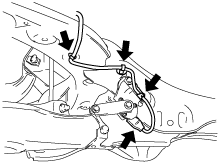
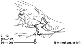
2. Disconnect the wiring harness clips and connector installed to the rear crossmember. (With auto leveling sensor)
am3uuw00011035
|
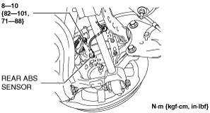
3. Disconnect the rear ABS wheel-speed sensor wiring harness installed to the hub support and set it aside. (See REAR ABS WHEEL-SPEED SENSOR REMOVAL/INSTALLATION.)
am3uuw00011339
|
4. Remove the presilencer. (MZR 1.6) (See EXHAUST SYSTEM REMOVAL/INSTALLATION [MZR 1.6].)
5. Remove the TWC. (SKYACTIV-G 1.5, SKYACTIV-G 2.0, SKYACTIV-G 2.5) (See EXHAUST SYSTEM REMOVAL/INSTALLATION [SKYACTIV-G 1.5, SKYACTIV-G 2.0, SKYACTIV-G 2.5].)
6. Remove the middle pipe. (SKYACTIV-D 1.5, SKYACTIV-D 2.2) (See EXHAUST SYSTEM REMOVAL/INSTALLATION [SKYACTIV-D 1.5].) (See EXHAUST SYSTEM REMOVAL/INSTALLATION [SKYACTIV-D 2.2].)
7. Remove the rear coil spring. (See REAR COIL SPRING REMOVAL/INSTALLATION.)
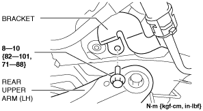
8. Set the bracket aside.
am3uuw00012098
|
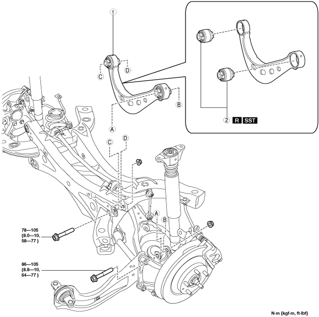
9. Remove in the order indicated in the table.
10. Install in the reverse order of removal.
11. Inspect the wheel alignment and adjust it if necessary. (See REAR WHEEL ALIGNMENT.)
am3uuw00011036
|
|
1
|
Rear upper arm
(See Rear Upper Arm Removal Note.)
|
|
2
|
Rear upper arm bushing
|
Rear Upper Arm Removal Note
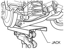
1. Jack up the vehicle to the unloaded condition, and support the rear trailing link component using a jack.
ac5wzw00002864
|
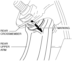
2. Align the rear crossmember component and rear upper arm and mark them.
ac5uuw00000181
|
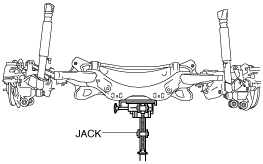
3. Support the rear crossmember component with a jack and remove the rear crossmember installation nuts.
am3uuw00011037
|
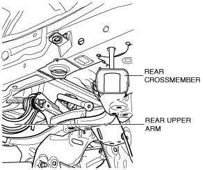
4. Press down on the rear crossmember component slowly until the rear upper arm inside installation bolts can be removed using a jack.
am3uuw00011038
|
5. Remove the rear upper arm.
Rear Upper Arm Bushing Removal Note
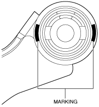
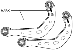
1. Mark the rear upper arm as shown in the figure.
am3uuw00011039
|
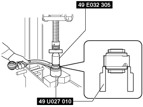
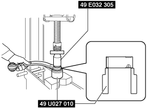
2. Press the rear upper arm bushing out using the SSTs.
am3uuw00011040
|
Rear Upper Arm Bushing Installation Note
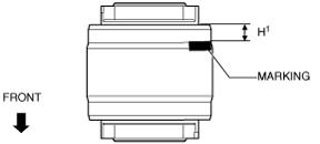
1. Mark the new rear upper arm bushing as shown in the figure.
am3uuw00011041
|
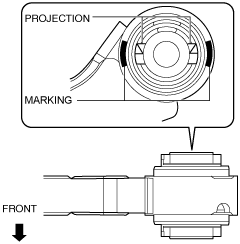
2. Align the projection of a new rear upper arm bushing with the marks placed during removal.
am3uuw00011042
|
3. Press fit the rear upper arm bushing until the marks placed in Step 1 cannot be seen using the SSTs.
am3uuw00011043
|
ac5wzw00002158
|
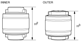
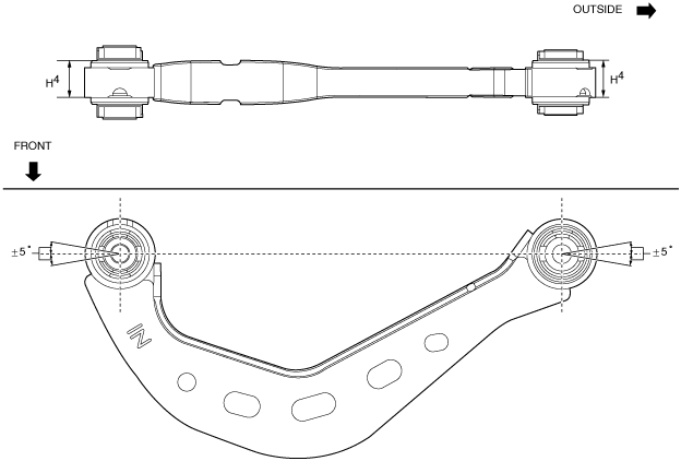
4. After installing the rear upper arm bushing, verify that it is installed to the position shown in the figure.
am3uuw00011044
|
Rear Upper Arm Installation Note
1. Place alignment mark on the new rear upper arm in the same positions as the removed rear upper arm.
am3uuw00011045
|
2. Install the rear upper arm.
3. Lift up the rear crossmember component using a jack and install the rear crossmember installation nuts.
am3uuw00011037
|