DTC U3003:08/U3003:16/U3003:17 [DYNAMIC STABILITY CONTROL (DSC)]


id0402b2902000

DTC
U3003:08, U3003:16, U3003:17
Power supply system
DETECTION CONDITION
•  U3003:08
―  While the vehicle is traveling at a speed of 10km/h {6.2 mph} or more, a CAN signal error caused by low power supply voltage is detected.
•  U3003:16
―  Low ignition voltage (7.9—9.6 V) is detected at the voltage monitor of the solenoid valve or motor monitor. (Except engine cranking condition)
―  Low ignition voltage (6.0—7.9 V) is detected at the voltage monitor of the solenoid valve or motor monitor.
―  Low ignition voltage (below 6.0 V) is detected at the voltage monitor of the solenoid valve or motor monitor.
•  U3003:17
―  High ignition voltage (17 V or more) is detected at the voltage monitor of the solenoid valve or motor monitor.
FAIL-SAFE FUNCTION
•  U3003:08
―  Permits the control and does not illuminate each warning/indicator light.
•  U3003:16
―  Illuminates the ABS warning light, TCS/DSC indicator light, Mazda Radar Cruise Control (MRCC) warning light*1, and Smart Brake Support/Smart City Brake Support (SBS/SCBS) indicator light (amber)*1.
―  Does not illuminate the brake warning light.*2
―  Illuminates the brake warning light.*3*4
―  Tire pressure monitoring system warning light*1 illuminates after flashes.
―  Inhibits the ABS, TCS, DSC, brake assist control, vehicle roll prevention function*1, Hill Launch Assist (HLA), TPMS*1, Secondary Collision Reduction (SCR)*1, Mazda Radar Cruise Control (MRCC)*1, Smart Brake Support (SBS)*1, and Smart City Brake Support (SCBS)*1 controls.
―  Permits the EBD control.*2
―  Inhibits the EBD control.*3*4
•  U3003:17
―  Illuminates the ABS warning light, brake system warning light, TCS/DSC indicator light, Mazda Radar Cruise Control (MRCC) warning light*1, and Smart Brake Support/Smart City Brake Support (SBS/SCBS) indicator light (amber)*1.
―  Tire pressure monitoring system warning light*1 illuminates after flashes.
―  Inhibits the ABS, EBD, TCS, DSC, brake assist control, vehicle roll prevention function*1, Hill Launch Assist (HLA), TPMS*1, Secondary Collision Reduction (SCR)*1, Mazda Radar Cruise Control (MRCC)*1, Smart Brake Support (SBS)*1, and Smart City Brake Support (SCBS)*1, controls.
*1: If equipped.
*2: When power supply voltage is 7.9—9.6 V for 700 ms or more.
*3: When power supply voltage is 6.0—7.9 V for 780 ms or more.
*4: When power supply voltage is below 6 V for 50 ms or more.
POSSIBLE CAUSE
•  Battery deterioration
•  Generator malfunction
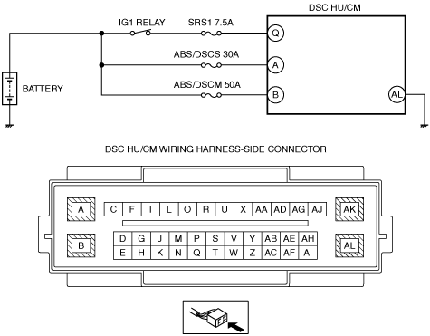
•  Fuse (SRS1 7.5A, ABS/DSCS 30A, ABS/DSCM 50A) malfunction
•  Open or short circuit in wiring harness between DSC HU/CM terminal A and battery
•  Open or short circuit in wiring harness between DSC HU/CM terminal B and battery
•  Open or short circuit in wiring harness between DSC HU/CM terminal Q and battery
•  Open circuit in wiring harness between DSC HU/CM terminal AL and body ground
•  Poor connection at connectors (female terminal)

Diagnostic procedure

STEP

INSPECTION

ACTION

1
INSPECT BATTERY VOLTAGE
•  Is the battery positive terminal voltage normal?
Yes
Inspect for normal connection of the battery terminals.
Go to the next step.
No
Charge or replace the battery, then go to Step 7.
2
INSPECT BATTERY GRAVITY
•  Is battery specific gravity as specified?
Yes
Go to the next step.
No
Replace the battery, then go to Step 7.
3
INSPECT CHARGING SYSTEM
•  Are the generator and the drive belt tensions normal?
Yes
Go to the next step.
No
Replace the generator and/or drive belt if necessary.
Go to Step 7.
4
INSPECT FUSE CONDITION
•  Inspect the following fuses.
―  SRS1 7.5A
―  ABS/DSCS 30A
―  ABS/DSCM 50A
•  Is the fuse normal?
Yes
Go to the next step.
No
Replace the fuse, then go to Step 7.
5
INSPECT DSC HU/CM POWER SUPPLY FOR OPEN CIRCUIT
•  Disconnect the DSC HU/CM connectors.
•  Switch the ignition ON (engine off).
•  Measure the voltage between following connector terminals of the DSC HU/CM (vehicle harness-side) and body ground:
―  DSC HU/CM: A—Body ground
―  DSC HU/CM: B—Body ground
―  DSC HU/CM: Q—Body ground
•  Is the voltage 10 V or more?
Yes
Go to the next step.
No
Refer to the wiring diagram and verify whether or not there is a common connector between following connector terminals of the DSC HU/CM (vehicle harness-side) and positive battery terminal:
―  DSC HU/CM: A—Positive battery terminal
―  DSC HU/CM: B—Positive battery terminal
―  DSC HU/CM: Q—Positive battery terminal
If there is a common connector:
•  Determine the malfunctioning part by inspecting the common connector and the terminal for corrosion, damage, or pin disconnection, and the common wiring harness for an open circuit.
•  Repair or replace the malfunctioning part.
If there is no common connector:
•  Repair or replace the wiring harness which has an open circuit.
Go to Step 7.
6
INSPECT DSC HU/CM GROUND FOR POOR GROUND OR OPEN CIRCUIT
•  Switch the ignition to off.
•  Measure the resistance between the DSC HU/CM terminal AL (vehicle harness-side) and body ground.
•  Is the resistance within 0—1 ohm?
Yes
Go to the next step.
No
•  If there is open circuit:
―  Refer to the wiring diagram and verify whether or not there is a common connector between DSC HU/CM terminal AL and the body ground.
If there is a common connector:
•  Determine the malfunctioning part by inspecting the common connector and the terminal for corrosion, damage, or pin disconnection, and the common wiring harness for an open circuit.
•  Repair or replace the malfunctioning part.
If there is no common connector:
•  Repair or replace the wiring harness which has an open circuit.
―  Go to the next step.
•  If resistance is not within specification:
―  Refer to the wiring diagram and verify whether or not there is a common connector between DSC HU/CM terminal AL and the body ground.
If there is a common connector:
•  Determine the malfunctioning part by inspecting the common connector and the terminal for corrosion, damage, or pin disconnection, and the common wiring harness for poor ground.
•  Repair or replace the malfunctioning part.
If there is no common connector:
•  Repair or replace the poor ground part.
―  Go to the next step.
7
VERIFY THAT THE SAME DTC IS NOT PRESENT
•  Reconnect all disconnected connectors.
•  Clear the DTCs from the memory.
•  Start the engine and drive the vehicle at 20 km/h {12 mph} or more.
•  Are the same DTCs present?
Yes
Repeat the inspection from Step 1.
No
Go to the next step.
8
VERIFY THAT NO OTHER DTCS ARE PRESENT
•  Are any other DTCs output?
Yes
Go to the applicable DTC inspection.
No
DTC troubleshooting completed.