POWER BRAKE UNIT REMOVAL/INSTALLATION [L.H.D.]
id041100801850
-
Caution
-
• Once the brake switch clearance has automatically been adjusted, it cannot be adjusted again. Therefore, replace the switch with a new one when replacing the power brake unit or performing any procedure that changes the brake pedal stroke.
1. For MZR 1.6, SKYACTIV-G 1.5, or SKYACTIV-G 2.0, perform the following procedure:
- (1) Remove the windshield wiper arm and blade. (See WINDSHIELD WIPER ARM AND BLADE REMOVAL/INSTALLATION.)
-
- (2) Remove the cowl grille. (See COWL GRILLE REMOVAL/INSTALLATION.)
-
- (3) Remove the windshield wiper motor and link. (See WINDSHIELD WIPER MOTOR AND LINK REMOVAL/INSTALLATION.)
-
- (4) Remove the cowl panel. (See COWL PANEL REMOVAL/INSTALLATION.)
-
2. For SKYACTIV-D 2.2, perform the following procedure:
- (1) Remove the battery. (See BATTERY REMOVAL/INSTALLATION [SKYACTIV-D 2.2].)
-
- (2) Remove the windshield wiper arm and blade. (See WINDSHIELD WIPER ARM AND BLADE REMOVAL/INSTALLATION.)
-
- (3) Remove the cowl grille. (See COWL GRILLE REMOVAL/INSTALLATION.)
-
- (4) Remove the windshield wiper motor and link. (See WINDSHIELD WIPER MOTOR AND LINK REMOVAL/INSTALLATION.)
-
- (5) Remove the cowl panel. (See COWL PANEL REMOVAL/INSTALLATION.)
-
3. For SKYACTIV-D 1.5, perform the following procedure:
- (1) Remove the following parts:
-
- 1) Air cleaner cover (See INTAKE-AIR SYSTEM REMOVAL/INSTALLATION [SKYACTIV-D 1.5].)
-
- 2) Air cleaner element (See INTAKE-AIR SYSTEM REMOVAL/INSTALLATION [SKYACTIV-D 1.5].)
-
- 3) Flesh-air duct (See INTAKE-AIR SYSTEM REMOVAL/INSTALLATION [SKYACTIV-D 1.5].)
-
- 4) Air cleaner case (See INTAKE-AIR SYSTEM REMOVAL/INSTALLATION [SKYACTIV-D 1.5].)
-
- 5) Air hose (See INTAKE-AIR SYSTEM REMOVAL/INSTALLATION [SKYACTIV-D 1.5].)
-
- 6) Air inlet pipe (See INTAKE-AIR SYSTEM REMOVAL/INSTALLATION [SKYACTIV-D 1.5].)
-
- (2) Remove the battery and battery tray. (See BATTERY REMOVAL/INSTALLATION [SKYACTIV-D 1.5].)
-
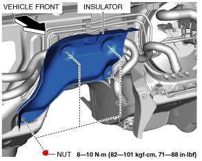
- (3) Remove the nuts.
-
- (4) Remove the insulator.
-
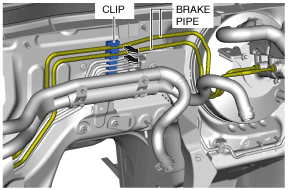
- (5) Remove the brake pipes from the clip.
-
4. Remove the master cylinder. (See MASTER CYLINDER REMOVAL/INSTALLATION [L.H.D.].)
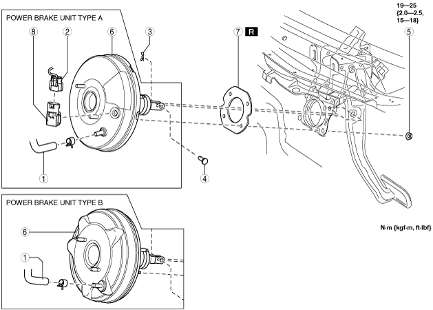
5. Remove in the order indicated in the table.
6. Install in the reverse order of removal.
7. After installation, add brake fluid, bleed the air, and inspect for fluid leakage. (See BRAKE FLUID AIR BLEEDING.)
8. Remove the brake switch. (See BRAKE PEDAL REMOVAL/INSTALLATION [L.H.D.].)
9. Inspect the brake pedal. (See BRAKE PEDAL INSPECTION.)
10. Install a new brake switch. (See BRAKE PEDAL REMOVAL/INSTALLATION [L.H.D.].)
-
Note
-
• Verify the shape of the power brake unit shown in the figure to determine type A or B.
|
1
|
Vacuum hose
|
|
2
|
Power brake unit vacuum sensor connector (vehicles with i-stop)
|
|
3
|
Snap pin
|
|
4
|
Clevis pin
|
|
5
|
Nut
|
|
6
|
Power brake unit
|
|
7
|
Gasket
|
|
8
|
Power brake unit vacuum sensor (vehicles with i-stop)
|