 |
am6zzw00009015
OIL COOLER REMOVAL/INSTALLATION [FW6A-EL]
id0517h1117500
Water Hose
1. Disconnect the negative battery cable. (See NEGATIVE BATTERY CABLE DISCONNECTION/CONNECTION [SKYACTIV-G 1.5, SKYACTIV-G 2.0, SKYACTIV-G 2.5].)
2. Remove the air cleaner and air hose as a single unit. (See INTAKE-AIR SYSTEM REMOVAL/INSTALLATION [SKYACTIV-G 1.5, SKYACTIV-G 2.0, SKYACTIV-G 2.5].)
3. Remove the battery tray and PCM component. (See BATTERY REMOVAL/INSTALLATION [SKYACTIV-G 1.5, SKYACTIV-G 2.0, SKYACTIV-G 2.5].)
4. Remove the front under cover No.2. (See FRONT UNDER COVER No.1 REMOVAL/INSTALLATION.)
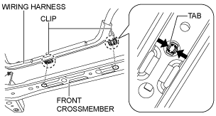
5. Disconnect the wiring harness from the front crossmember. (Vehicle with i-ELOOP)
am6zzw00009015
|
6. Drain the engine coolant. (See ENGINE COOLANT REPLACEMENT [SKYACTIV-G 1.5, SKYACTIV-G 2.0, SKYACTIV-G 2.5].)
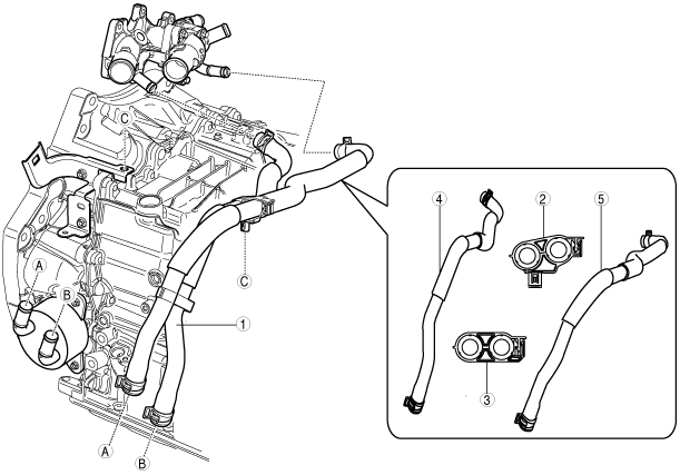
7. Remove in the order indicated in the table.
am6zzw00009016
|
|
1
|
Water hose component
|
|
2
|
Hose clip No.1
|
|
3
|
Hose clip No.2
|
|
4
|
Water hose No.1
|
|
5
|
Water hose No.2
|
8. Install in the reverse order of removal.
9. Add the engine coolant. (See ENGINE COOLANT REPLACEMENT [SKYACTIV-G 1.5, SKYACTIV-G 2.0, SKYACTIV-G 2.5].)
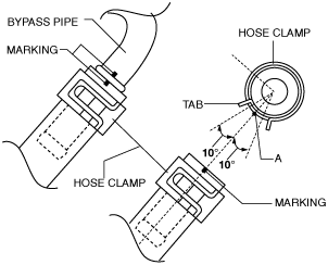
Water Hose No.1 and No.2 (oil cooler side) Installation Note
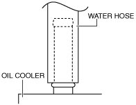
1. Install the water hose to the oil cooler as shown in the figure with the hose clamp expanded.
am3uuw00008323
|
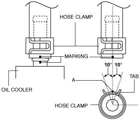
2. Install the hose clamp so that center A of the hose clamp tab is within the range shown in the figure.
am6zzw00009017
|
3. Verify that the hose clamp does not interfere with any other components.
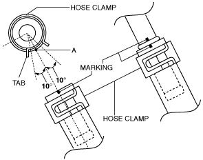
Water Hose No.1 (outlet case side) Installation Note
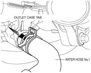
1. Install the water hose No.1 to the outlet case as shown in the figure with the hose clamp expanded.
am6zzw00009018
|
2. Install the hose clamp so that center A of the hose clamp tab is within the range shown in the figure.
am6zzw00009019
|
3. Verify that the hose clamp does not interfere with any other components.
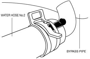
Water Hose No.2 (bypass pipe side) Installation Note
1. Install the water hose No.2 to the bypass pipe as shown in the figure with the hose clamp expanded.
am6zzw00009020
|
2. Install the hose clamp so that center A of the hose clamp tab is within the range shown in the figure.
am6zzw00009021
|
3. Verify that the hose clamp does not interfere with any other components.
Oil Cooler
1. Disconnect the negative battery cable. (See NEGATIVE BATTERY CABLE DISCONNECTION/CONNECTION [SKYACTIV-G 1.5, SKYACTIV-G 2.0, SKYACTIV-G 2.5].)
2. Remove the front under cover No.2. (See FRONT UNDER COVER No.1 REMOVAL/INSTALLATION.)
3. Drain the ATF. (See AUTOMATIC TRANSAXLE FLUID (ATF) REPLACEMENT [FW6A-EL].)
4. Disconnect the wiring harness from the front crossmember. (Vehicle with i-ELOOP)
am6zzw00009015
|
5. Drain the engine coolant. (See ENGINE COOLANT REPLACEMENT [SKYACTIV-G 1.5, SKYACTIV-G 2.0, SKYACTIV-G 2.5].)
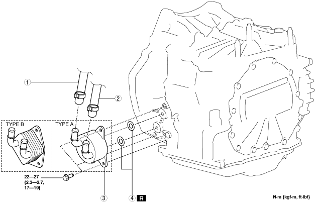
6. Remove in the order indicated in the table.
am3uuw00013773
|
|
1
|
Water hose No.1
|
|
2
|
Water hose No.2
|
|
3
|
Water-cooled oil cooler
• Type A: cylindrical oil cooler
• Type B: cubic-shaped oil cooler
|
|
4
|
O-rings
|
7. Install in the reverse order of removal.
8. Add the engine coolant. (See ENGINE COOLANT REPLACEMENT [SKYACTIV-G 1.5, SKYACTIV-G 2.0, SKYACTIV-G 2.5].)
9. Add the ATF. (See AUTOMATIC TRANSAXLE FLUID (ATF) REPLACEMENT [FW6A-EL].)
10. Perform the “Mechanical System Test”. (See MECHANICAL SYSTEM TEST [FW6A-EL].)