CONTROL VALVE BODY REMOVAL/INSTALLATION [CW6A-EL]
id0517l1118000
On-Vehicle Removal
-
Warning
-
• A hot transaxle and ATF can cause severe burns. Turn off the engine and wait until they are cool.
• Using compressed air can cause dirt and other particles to fly out, causing injury to the eyes. Wear protective eyeglasses whenever using compressed air.
-
Caution
-
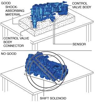
• If the control valve body is placed with the shift solenoid side facing down on a workbench, the wiring harness or connector of the coupler component may be damaged. When placing the control valve body on a workbench, always place it with the control valve body connector side facing down. However if the control valve body is directly placed on the workbench, the control valve body connector area or the sensor may be damaged. Always place the control valve body on an impact-absorbing material, which is free of foreign matter, so that the connector area and the sensor do not contact the workbench directly.
1. Select the selector lever to P position.
2. Disconnect the negative battery cable. (See NEGATIVE BATTERY CABLE DISCONNECTION/CONNECTION [SKYACTIV-G 1.5, SKYACTIV-G 2.0, SKYACTIV-G 2.5].)
3. Remove the front under cover No.2. (See FRONT UNDER COVER No.2 REMOVAL/INSTALLATION.)
4. Clean the transaxle exterior throughout with a steam cleaner or cleaning solvents.
5. Remove the air cleaner component. (See INTAKE-AIR SYSTEM REMOVAL/INSTALLATION [SKYACTIV-G 1.5, SKYACTIV-G 2.0, SKYACTIV-G 2.5].)
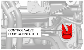
6. Disconnect the control valve body connector.
-
Caution
-
• Make sure that your hand does not touch the terminal as the connector terminal could be damaged.
• Water or foreign objects entering the connector can cause a poor connection or corrosion. Be sure not to drop water or foreign objects on the connector when disconnecting it.
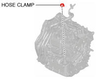
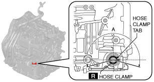
7. Remove the hose clamp.
8. Drain the ATF. (See AUTOMATIC TRANSAXLE FLUID (ATF) REPLACEMENT [CW6A-EL].)
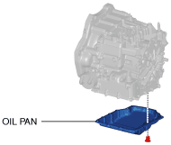
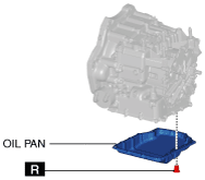
9. Remove the oil pan.
-
Note
-
• Always use new oil pan installation bolts when re-installing the oil pan because the oil pan installation bolts cannot be reused.
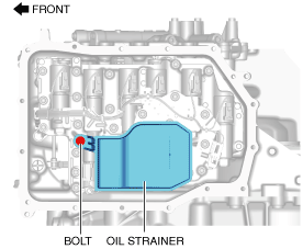
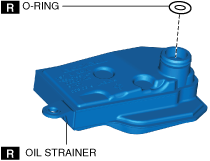
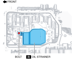
10. Remove the oil strainer.
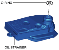
11. Remove the oil strainer O-ring.
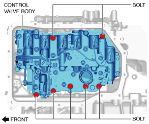
12. Remove the control valve body.
-
Caution
-
• Remove the control valve body directly from underneath so that force is not applied to the control valve body connector in the lateral direction.
13. Remove the oil seal (control valve body). (See OIL SEAL (CONTROL VALVE BODY) REPLACEMENT [CW6A-EL].)
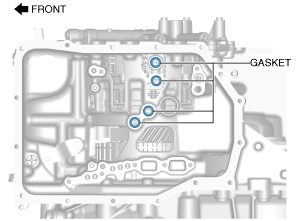
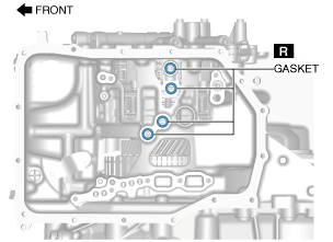
14. Remove the gasket from the transaxle case.
On-Vehicle Installation
1. Install the gasket to the transaxle case.
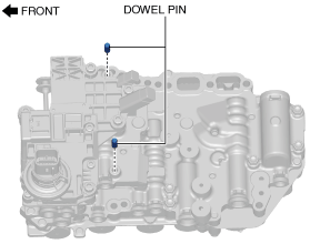
2. Install the dowel pin to the control valve body.
-
Note
-
• Oil with a color different from the genuine ATF may be adhered to a new control valve body.
• If the dowel pin remains in the transaxle case, remove the dowel pin from the transaxle case and install the dowel pin to the control valve body.
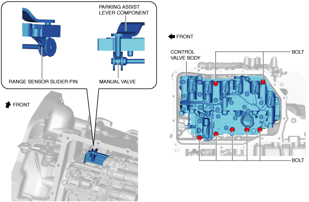
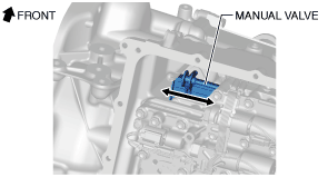
3. Install the control valve body so that the parking assist lever component and range sensor slider pin are engaged in the gap between the two surfaces of the spool part of the manual valve.
-
Caution
-
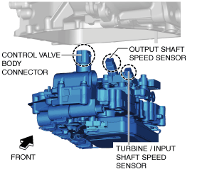
• Install the control valve body so that the turbine/input shaft speed sensor, output shaft speed sensor, and control valve body connector do not contact the transaxle case.
-
Tightening torque
-
9—10 N·m {92—101 kgf·cm, 80—88 in·lbf}
4. Move the manual valve in both directions of the arrow and verify that the manual valve is correctly connected to the parking assist lever component and the slider pin for the range sensor.
-
Note
-
• If the manual valve only moves in the gap between the parking assist lever component surface and the manual valve surface, the manual valve and the parking assist lever component are correctly engaged.
5. Install the oil strainer O-rings.
6. Install the oil strainer.
-
Tightening torque
-
9—10 N·m {92—101 kgf·cm, 80—88 in·lbf}
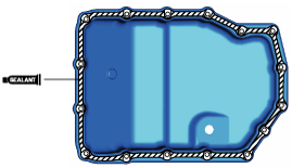
7. Apply a light coat of silicone sealant (TB1217E or equivalent) to the contact surfaces of the oil pan and transaxle case.
-
Caution
-
• Clean any remaining silicone sealant on the contact surface of the transaxle case and oil pan, and degrease the sealant area. Otherwise, oil could leak.
8. Install the oil pan with new bolts before the applied sealant starts to harden.
-
Tightening torque
-
8—10 N·m {82—101 kgf·cm, 71—88 in·lbf}
9. Install the oil seal (control valve body). (See OIL SEAL (CONTROL VALVE BODY) REPLACEMENT [CW6A-EL].)
10. Install a new hose clamp to the position shown in the figure.
-
Caution
-
• If the hose clamp is reused it could cause ATF leakage, therefore use a new hose clamp.
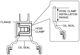
• Install the hose clamp tab to within the range shown in the figure.
A: 210°
• Install the hose clamp so that it does not interfere with the top and bottom flanges of the oil seal to maintain the waterproofing integrity.
11. Connect the control valve body connector.
-
Caution
-
• Make sure that your hand does not touch the terminal as the connector terminal could be damaged.
• Verify that there is no fluid or foreign matter adhering to the connector before connecting the connector.
• Insert the connector straight as the connector terminal could be damaged.
• Rotate the connector lever until a click is heard.
12. Add the ATF. (See AUTOMATIC TRANSAXLE FLUID (ATF) REPLACEMENT [CW6A-EL].)
13. Install the air cleaner component. (See INTAKE-AIR SYSTEM REMOVAL/INSTALLATION [SKYACTIV-G 1.5, SKYACTIV-G 2.0, SKYACTIV-G 2.5].)
14. Connect the negative battery cable. (See NEGATIVE BATTERY CABLE DISCONNECTION/CONNECTION [SKYACTIV-G 1.5, SKYACTIV-G 2.0, SKYACTIV-G 2.5].)
15. Perform the “TCM configuration” (Control valve body Replacement). (See TCM CONFIGURATION [CW6A-EL].)
-
Caution
-
• The transaxle does not operate normally if the TCM configuration is not performed. When the control valve body is replaced, always perform the TCM configuration to enable the transaxle to operate normally.
• When the control valve body is replaced, a U-code DTC is output. After completing the TCM configuration, clear the U-code DTC and verify that no DTCs are output.
16. Perform the “Initial Learning” (Control valve body Replacement). (See INITIAL LEARNING [CW6A-EL].)
17. Perform the “Mechanical System Test”. (See MECHANICAL SYSTEM TEST [CW6A-EL].)
18. Install the front under cover No.2. (See FRONT UNDER COVER No.2 REMOVAL/INSTALLATION.)
19. Perform the “Road Test”. (See ROAD TEST [CW6A-EL].)