 |
am6zzw00010703
PTC (POSITIVE TEMPERATURE COEFFICIENT) HEATER INSPECTION
id071100002900
am6zzw00010703
|
Step 1
1. Remove the side wall (passenger side). (See SIDE WALL REMOVAL/INSTALLATION.)
2. Connect the M-MDS to the DLC-2.
3. After the vehicle is identified, select the following items from the initialization screen of the M-MDS.
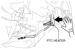
4. Operate the PTC heater using the PID “PTC_HEAT_ST”.
5. Touch the side surface of the PTC heater by hand to verify that it warms up.
am3zzw00015076
|
Step 2
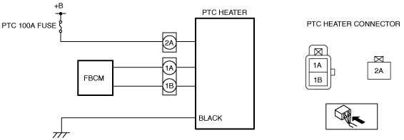
1. Measure the voltage of the PTC heater terminals 1A and 2A.
|
Terminal |
Signal name |
Connected to |
Measurement condition |
Voltage (V) |
Inspection item (s) |
|---|---|---|---|---|---|
|
1A
|
IG1
|
Front body control module (FBCM)
|
Switch the ignition ON (engine off)
|
B+
|
• Related wiring harness
• Front body control module (FBCM)
|
|
Switch the ignition off
|
1.0 or less
|
||||
|
2A
|
B+
|
• Battery
• PTC 100A fuse
|
Under any condition
|
B+
|
• Related wiring harness
• Battery
• PTC 100A fuse
|
Step 3
1. Operate the PTC heater using the PID “PTC_HEAT_ST”.
2. Measure the voltage at PTC heater terminal 1B while the PTC heater is operating.
Step 4
1. Switch the ignition off.
2. Disconnect the negative battery cable. (See NEGATIVE BATTERY CABLE DISCONNECTION/CONNECTION [SKYACTIV-D 2.2].)(See NEGATIVE BATTERY CABLE DISCONNECTION/CONNECTION [SKYACTIV-D 1.5].)
3. Remove the following parts:
4. Connect the negative battery cable.
5. Switch the ignition ON (engine off or on).
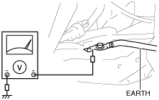
6. Operate the PTC heater using the PID “PTC_HEAT_ST”.
7. Measure the voltage at the ground of the PTC heater as shown in the figure.
am6zzw00010705
|