|
1
|
INSPECT INDICATOR UNIT CONNECTOR CONDITION
• Switch the ignition off.
• Disconnect the negative battery cable.
• Remove the climate control unit.
• Disconnect the indicator unit connector.
• Inspect the indicator unit connector. (Corrosion, damage, and disconnected pins)
• Is there any malfunction of the indicator unit connector?
|
Yes
|
Replace the malfunctioning part, then go to Step 6.
|
|
No
|
Go to the next step.
|
|
2
|
INSPECT INSTRUMENT CLUSTER CONNECTOR CONDITION
• Disconnect the instrument cluster connector.
• Inspect the connector engagement and connection condition and inspect the terminals for damage, deformation, corrosion, or disconnection.
• Is the connector normal?
|
Yes
|
Go to the next step.
|
|
No
|
Repair or replace the connector, then go to Step 6.
|
|
3
|
INSPECT INDICATOR UNIT CIRCUIT FOR OPEN CIRCUIT
• Indicator unit and instrument cluster connectors are disconnected.
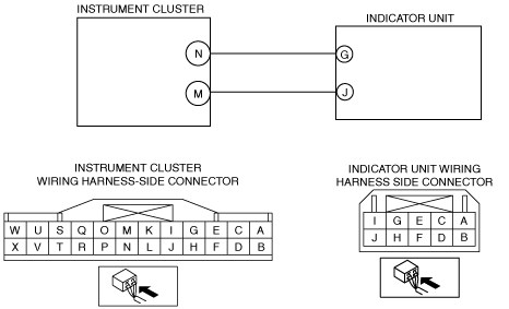
• Inspect for continuity between the following terminals (wiring harness-side):
-
― Indicator unit terminal G—instrument cluster N
― Indicator unit terminal J—instrument cluster M
-
Note
-
• Inspect for continuity while shaking the wiring harness between the instrument cluster and indicator unit.
• Is there continuity?
|
Yes
|
Go to the next step.
|
|
No
|
Refer to the wiring diagram and verify whether or not there is a common connector between instrument cluster and indicator unit.
If there is a common connector:
• Determine the malfunctioning part by inspecting the common connector and the terminal for corrosion, damage, or pin disconnection, and the common wiring harness for an open circuit.
• Replace the malfunctioning part.
If there is no common connector:
• Replace the wiring harness which has an open circuit.
Go to Step 6.
|
|
4
|
INSPECT INDICATOR UNIT CIRCUIT FOR SHORT TO POWER SUPPLY
• Indicator unit and instrument cluster connectors are disconnected.
• Connect the negative battery cable.
• Switch the ignition ON (engine off or on).
• Measure the voltage at the following terminals (wiring harness-side):
-
― Indicator unit terminal G
― Indicator unit terminal J
-
Note
-
• Measure the voltage while shaking the wiring harness between the instrument cluster and indicator unit.
• Is the voltage 0 V?
|
Yes
|
Go to the next step.
|
|
No
|
Refer to the wiring diagram and verify whether or not there is a common connector between instrument cluster and indicator unit.
If there is a common connector:
• Determine the malfunctioning part by inspecting the common connector and the terminal for corrosion, damage, or pin disconnection, and the common wiring harness for a short to power supply.
• Replace the malfunctioning part.
If there is no common connector:
• Replace the wiring harness which has a short to power supply.
Go to Step 6.
|
|
5
|
INSPECT INDICATOR UNIT
• Inspect the indicator unit.
• Is it normal?
|
Yes
|
Go to the next step.
|
|
No
|
Replace the indicator unit, then go to the next step.
|
|
6
|
PERFORM SAS CONTROL MODULE DTC INSPECTION
• Reconnect all disconnected connectors.
• Connect the negative battery cable.
• Switch the ignition ON (engine off or on).
• Clear the DTC for the SAS control module using the M-MDS.
• Perform the DTC inspection for the SAS control module using the M-MDS.
• Are the same DTCs present?
|
Yes
|
Replace the SAS control module.
|
|
No
|
DTC troubleshooting completed.
|