BRAKE LIGHT UNIT INSPECTION


id091800400100

1.  Disconnect the negative battery cable. (See NEGATIVE BATTERY CABLE DISCONNECTION/CONNECTION [SKYACTIV-G 1.5, SKYACTIV-G 2.0, SKYACTIV-G 2.5].) (See NEGATIVE BATTERY CABLE DISCONNECTION/CONNECTION [SKYACTIV-D 2.2].)(See NEGATIVE BATTERY CABLE DISCONNECTION/CONNECTION [SKYACTIV-D 1.5].)

2.  Perform the following procedure.

4SD
1.  Remove the following parts.
(1) Rear scuff plate (See REAR SCUFF PLATE REMOVAL/INSTALLATION.)
(2) Rear seat cushion (See REAR SEAT CUSHION REMOVAL/INSTALLATION.)
(3) Rear seat back (See REAR SEAT BACK REMOVAL/INSTALLATION.)
(4) Tire house trim (See TIRE HOUSE TRIM REMOVAL/INSTALLATION.)
(5) C-pillar trim (See C-PILLAR TRIM REMOVAL/INSTALLATION.)
(6) High-mount brake light (See HIGH-MOUNT BRAKE LIGHT REMOVAL/INSTALLATION.)
(7) Rear package trim (See REAR PACKAGE TRIM REMOVAL/INSTALLATION.)
5HB
1.  Partially peel back the following parts.
(1) Tire house trim (LH) (See TIRE HOUSE TRIM REMOVAL/INSTALLATION.)
(2) Trunk side upper trim (LH) (See TRUNK SIDE UPPER TRIM REMOVAL/INSTALLATION.)
(3) Trunk side trim (LH) (See TRUNK SIDE TRIM REMOVAL/INSTALLATION.)

3.  Reconnect the negative battery cable. (See NEGATIVE BATTERY CABLE DISCONNECTION/CONNECTION [SKYACTIV-G 1.5, SKYACTIV-G 2.0, SKYACTIV-G 2.5].) (See NEGATIVE BATTERY CABLE DISCONNECTION/CONNECTION [SKYACTIV-D 2.2].)(See NEGATIVE BATTERY CABLE DISCONNECTION/CONNECTION [SKYACTIV-D 1.5].)

4.  Verify that the voltages of each of the terminals are as indicated in the terminal voltage table.

•  If the voltage is not as indicated in the table, inspect the parts under Inspection item (s).
―  If the system does not work normally even though the parts or related wiring harnesses do not have any malfunction, replace the brake light unit. (See BRAKE LIGHT UNIT REMOVAL/INSTALLATION.)

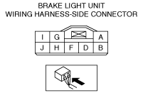
Terminal voltage list (reference)

am6zzw00009211

Terminal

Signal

Connection

Test condition

Voltage (V)

Inspection item(s)

A
Ground
Body ground
Under any condition
1.0 or less
Body ground
D
Brake light illumination request signal
Rear body control module (RBCM)
Because this terminal is for communication, good/no good judgment by terminal voltage is not possible.
F
Power supply
STOP 10 A fuse
Under any condition
B+
•  STOP 10 A fuse
•  Battery
G
High-mount brake light signal
High-mount brake light
Brake pedal depressed
B+
High-mount brake light
Brake pedal not depressed
1.0 or less
H
Brake light illumination status signal
DSC HU/CM
Brake pedal depressed
B+
DSC HU/CM
Brake pedal not depressed
1.0 or less
I
Brake switch (No.1 signal) signal
Brake switch (No.1 signal)
Brake pedal depressed
B+
Brake switch (No.1 signal)
Brake pedal not depressed
1.0 or less
J
Brake light signal
•  Brake light
•  Rear body control module (RBCM)
Brake pedal depressed
B+
•  Brake light
•  Rear body control module (RBCM)
Brake pedal not depressed
1.0 or less