 |
am3uuw00012378
ACTIVE DRIVING DISPLAY REMOVAL/INSTALLATION
id092200103700
Replacing Active Driving Display as Single Component
1. Disconnect the negative battery cable. (See NEGATIVE BATTERY CABLE DISCONNECTION/CONNECTION [SKYACTIV-D 2.2].) (See NEGATIVE BATTERY CABLE DISCONNECTION/CONNECTION [SKYACTIV-G 1.5, SKYACTIV-G 2.0, SKYACTIV-G 2.5].) (See NEGATIVE BATTERY CABLE DISCONNECTION/CONNECTION [MZR 1.6].)(See NEGATIVE BATTERY CABLE DISCONNECTION/CONNECTION [SKYACTIV-D 1.5].)
2. Remove the following parts:
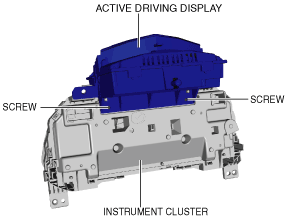
3. Remove the screws.
am3uuw00012378
|
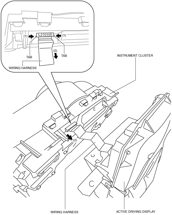
4. While pressing the instrument cluster tabs in the direction of arrows (1) shown in the figure, pull the wiring harness in the direction of arrow (2) and disconnect the wiring harness from the instrument cluster.
am3uuw00012379
|
5. Remove the active driving display.
6. Install in the reverse order of removal.(See Active Driving Display Installation Note.)
Active Driving Display Installation Note
am3uuw00014953
|
am3uuw00014954
|
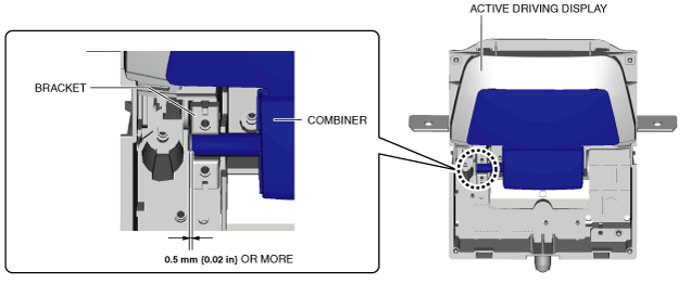
Replacing Combiner
1. Refer to ACTIVE DRIVING DISPLAY INSPECTION and stop the combiner at an angle of 10 degrees. (See ACTIVE DRIVING DISPLAY INSPECTION.)
2. Switch the ignition off.
3. Disconnect the negative battery cable. (See NEGATIVE BATTERY CABLE DISCONNECTION/CONNECTION [SKYACTIV-D 2.2].) (See NEGATIVE BATTERY CABLE DISCONNECTION/CONNECTION [SKYACTIV-G 1.5, SKYACTIV-G 2.0, SKYACTIV-G 2.5].) (See NEGATIVE BATTERY CABLE DISCONNECTION/CONNECTION [MZR 1.6].)(See NEGATIVE BATTERY CABLE DISCONNECTION/CONNECTION [SKYACTIV-D 1.5].)
4. Remove the following parts:
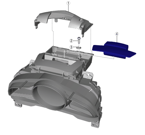
5. Remove the combiner in the following order:
am3uuw00011939
|
|
1
|
Cover
|
|
2
|
Screw
|
|
3
|
Spring
|
|
4
|
Combiner (See Combiner assembly note.)
|
6. Install in the reverse order of removal.
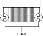
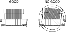
Combiner assembly note
am3zzw00014662
|